Tutorial 4 : Create Petri Model editor using the FreeModellingEditor
In this article, you will learn how to get started in creating a basic Petri Model Editor while using the FreeModellingEditor
1. Purpose of this tutorial
The purpose of this tutorial is:
- to discover how to elicit concepts from example use cases with the Openflexo FreeModellingEditor tool
- to build a basic graphical editor (diagram-based) of those concepts
- to be able to use FML language to define specific business logic for those concepts
2. About Petri Nets
https://en.wikipedia.org/wiki/Petri_net
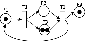
A Petri net, also known as a place/transition (PT) net, is one of several mathematical modeling languages for the description of distributed systems. It is a class of discrete event dynamic system. A Petri net is a directed bipartite graph, in which the nodes represent transitions (i.e. events that may occur, represented by bars) and places (i.e. conditions, represented by circles). The directed arcs describe which places are pre- and/or post-conditions for which transitions (signified by arrows). Some sources[1] state that Petri nets were invented in August 1939 by Carl Adam Petri—at the age of 13—for the purpose of describing chemical processes.
3. Download Openflexo
As a preliminary phase, you should get a recent Openflexo distribution
Download it on:
- https://www.openflexo.org/download.html
- Alternatively take the current 2.0.x snapshot (https://downloads.openflexo.org/openflexo/2.0.0SNAPSHOT/)
4. Launch Openflexo FreeModellingEditor and create a project
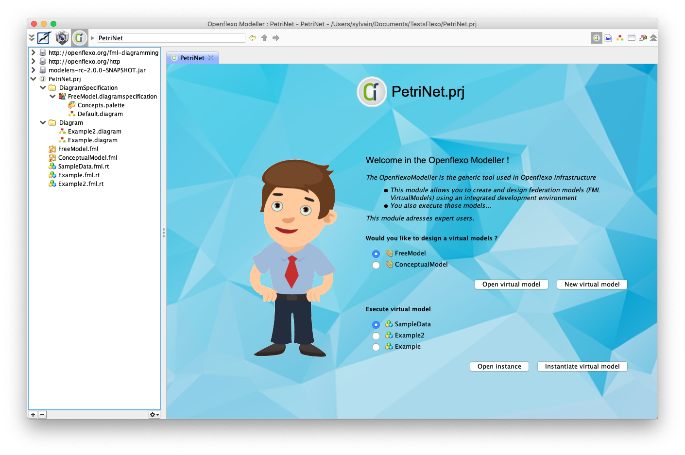
Launch Openflexo, and choose the FreeModellingEditor.
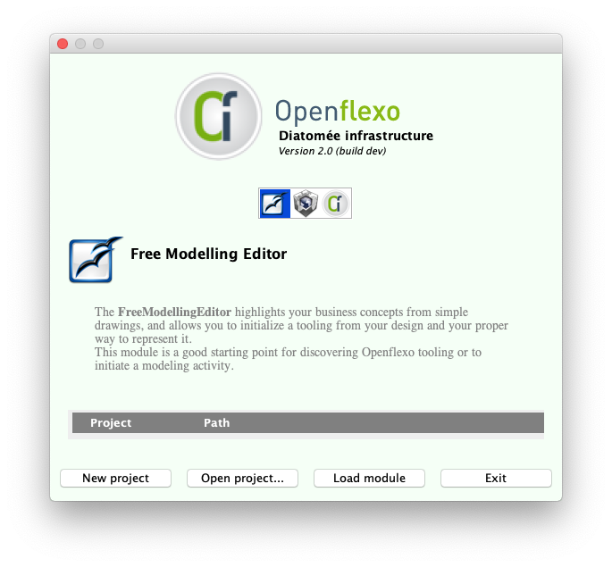
Select FreeModellingEditor icon.
Click on "New project", enter name, here "PetriNet".
The FreeModellingEditor module will be launched.
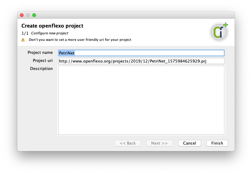
A windows opens, allowing to choose a URI and a description of project. Click on "Finish"
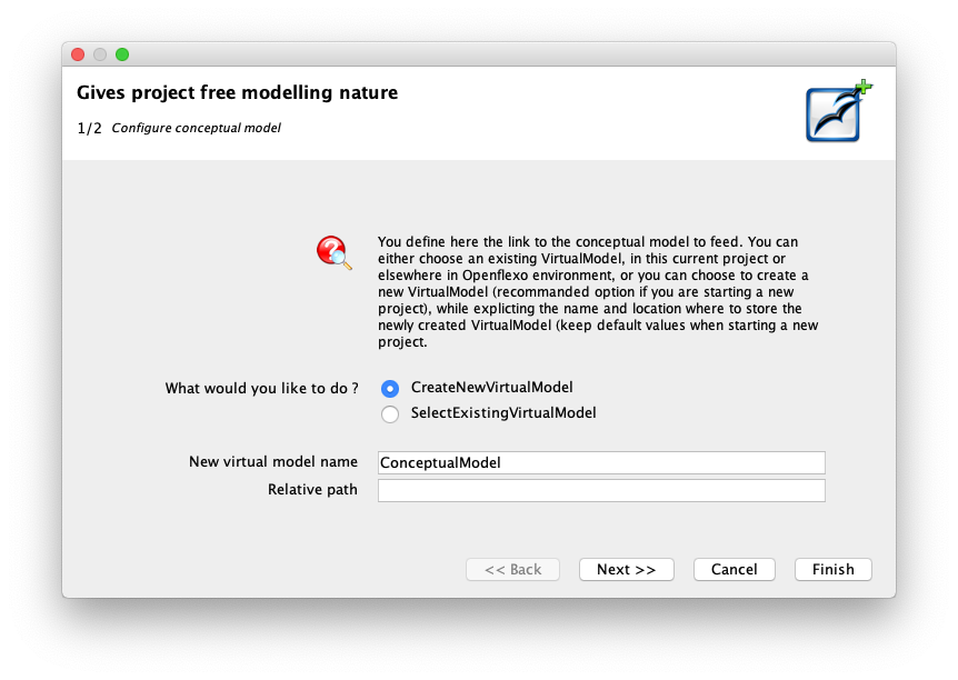
We choose to create new VirtualModel. This indicates that we would like to create a new Conceptual Model encoding Petri Net Model.
Click then on "Next"
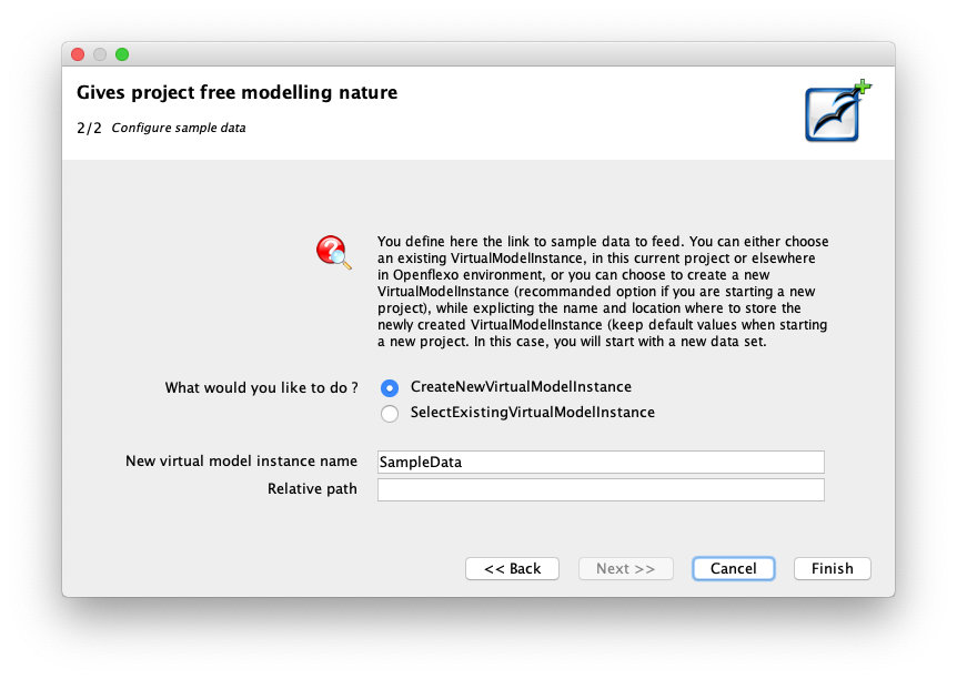
We choose to create new VirtualModelInstance: we would like to encode our own sample data.
Click then on "Finish"
The FreeModellingEditor module finally opens.
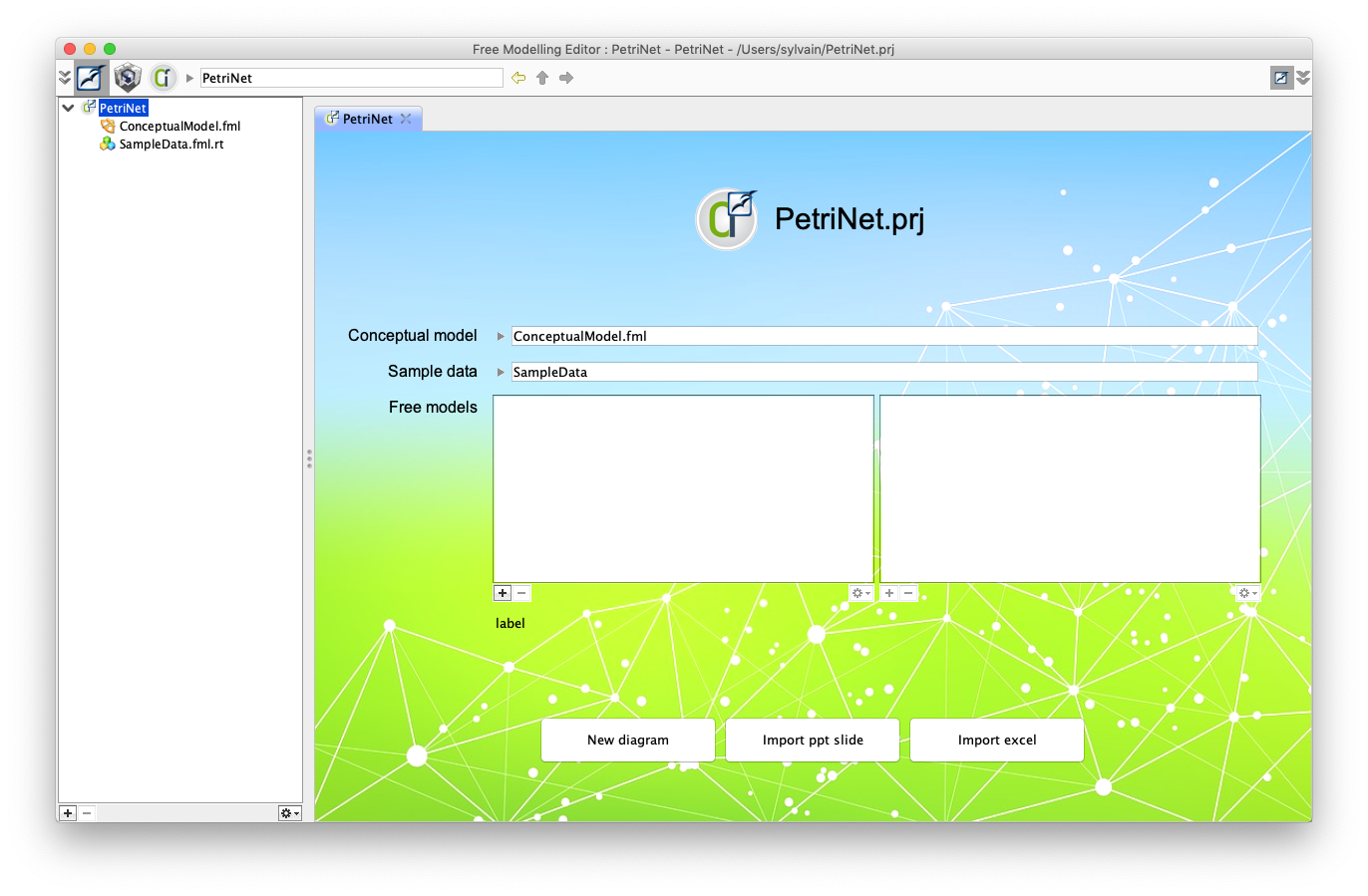
5. Create a FreeDiagram
We would like to elicit our Petri Net concepts from an example diagram.
Then click on "New diagram" to create a new example diagram.
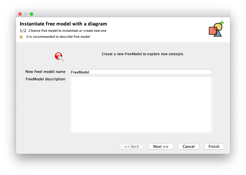
Type name of free model (keep same) and choose "Next".
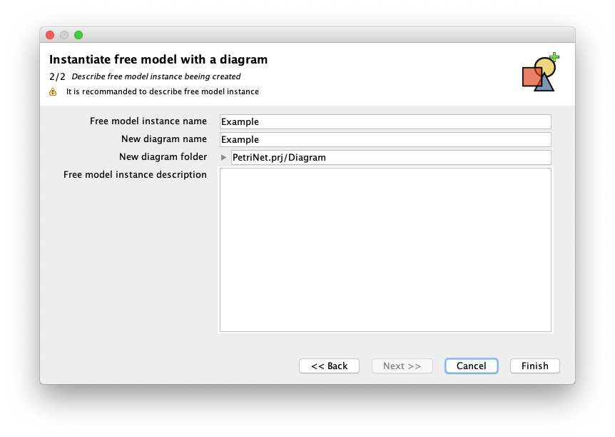
Type name of example (keep same) and choose "Finish".
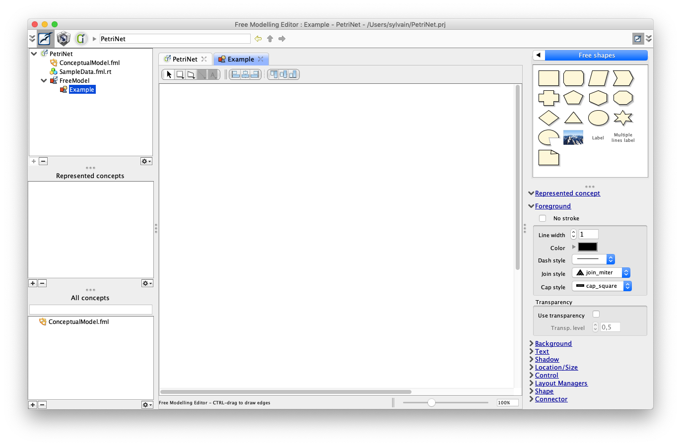
You should see this FreeDiagram panel.
6. Create a place
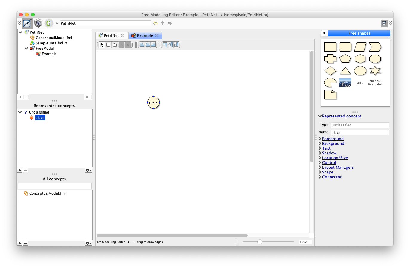
Drag an oval shape from the right palette, and name it "place".
Use graphical inspectors to set dimensions (40x40 pixels for example) foreground, background, text properties.
You should obtain this.
The place is here a pure shape, and has no particular meaning. Lets decide that we will elicit a concept from that shape.
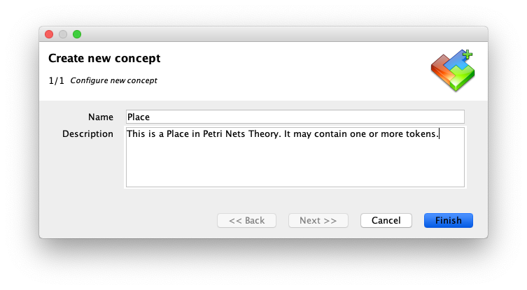
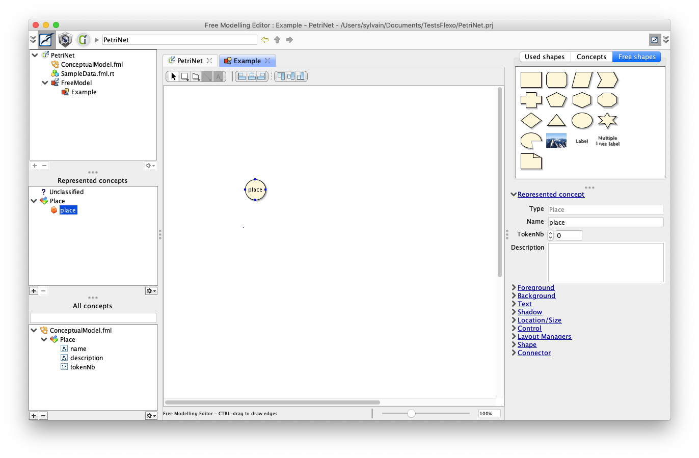
Right-click on the 'place' shape, and select "Create new concept"
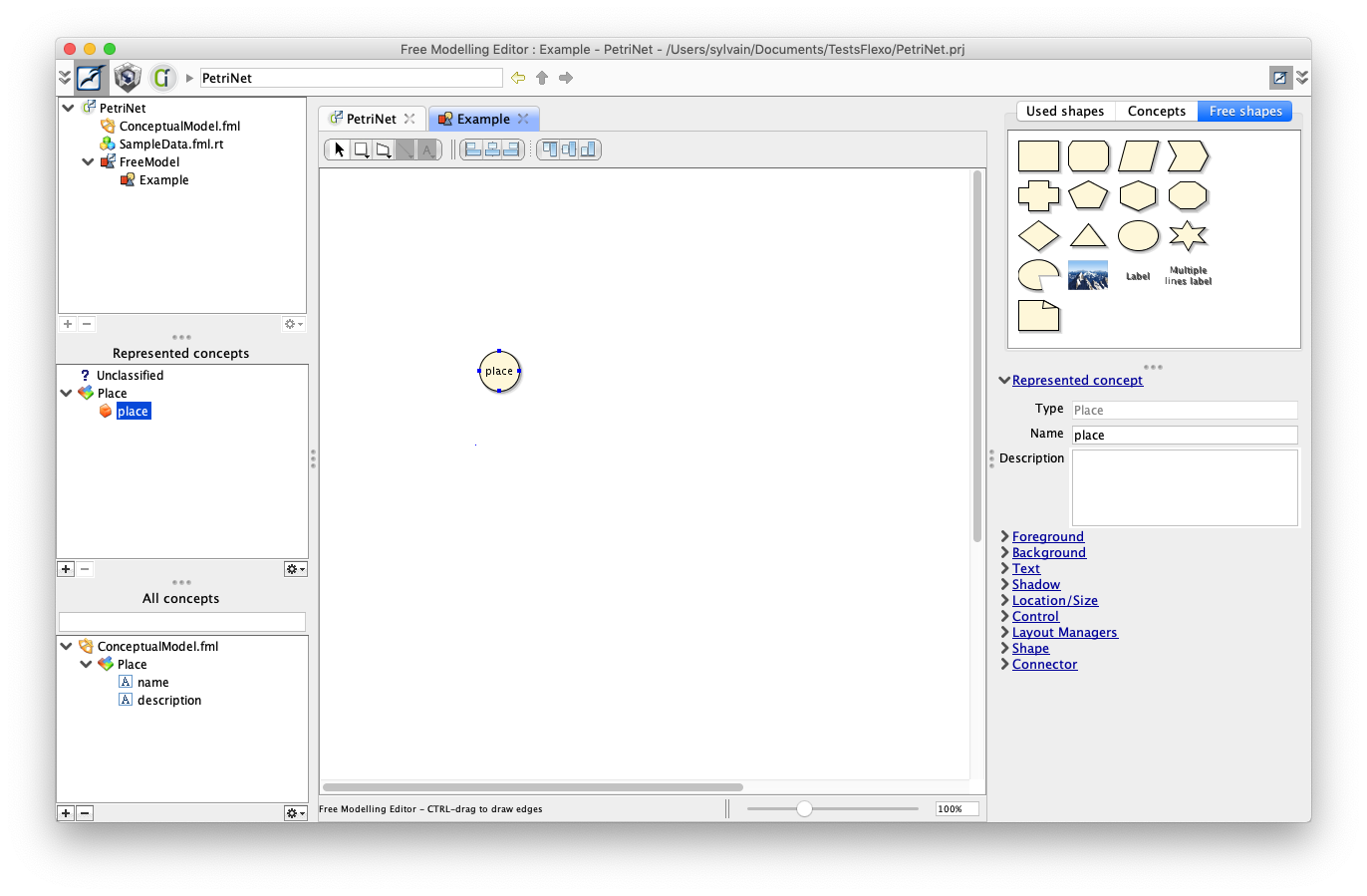
Concept 'Place' has been created in the conceptual model, with two default properties 'name' and 'description'. 'place' instance, represented as a shape, is now an instance of 'Place' concept.
We would like now to create a new property to 'Place' concept, as the number of tokens present in this place.
Right-click on 'place' instance and select 'Create new property'
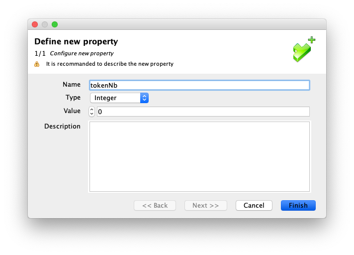
Property has been added to concept 'Place'. 'place' instance has now this property, and we can assign a value to that property (here the default number of tokens is '0').
7. Create a transition
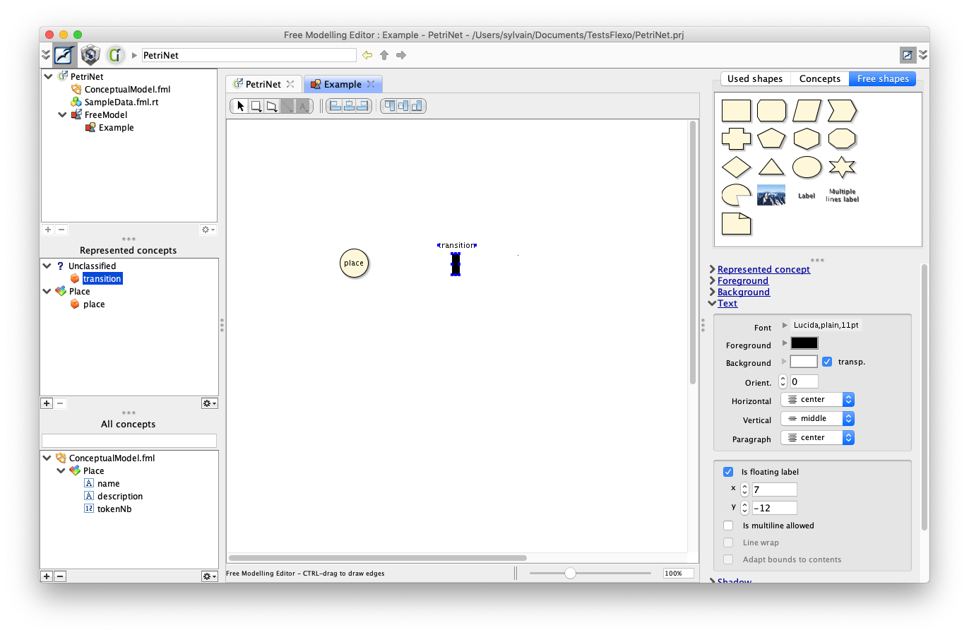
Now create a transition using the same scheme. Drag a rectangular shape from the right palette.
Use graphical inspectors to set dimensions (10x30 pixels for example) foreground (black color), background (black color), shadow (no shadow) and text properties.
In 'Text' inspector panel, you should check 'Is floating label'. Then you can move the label.
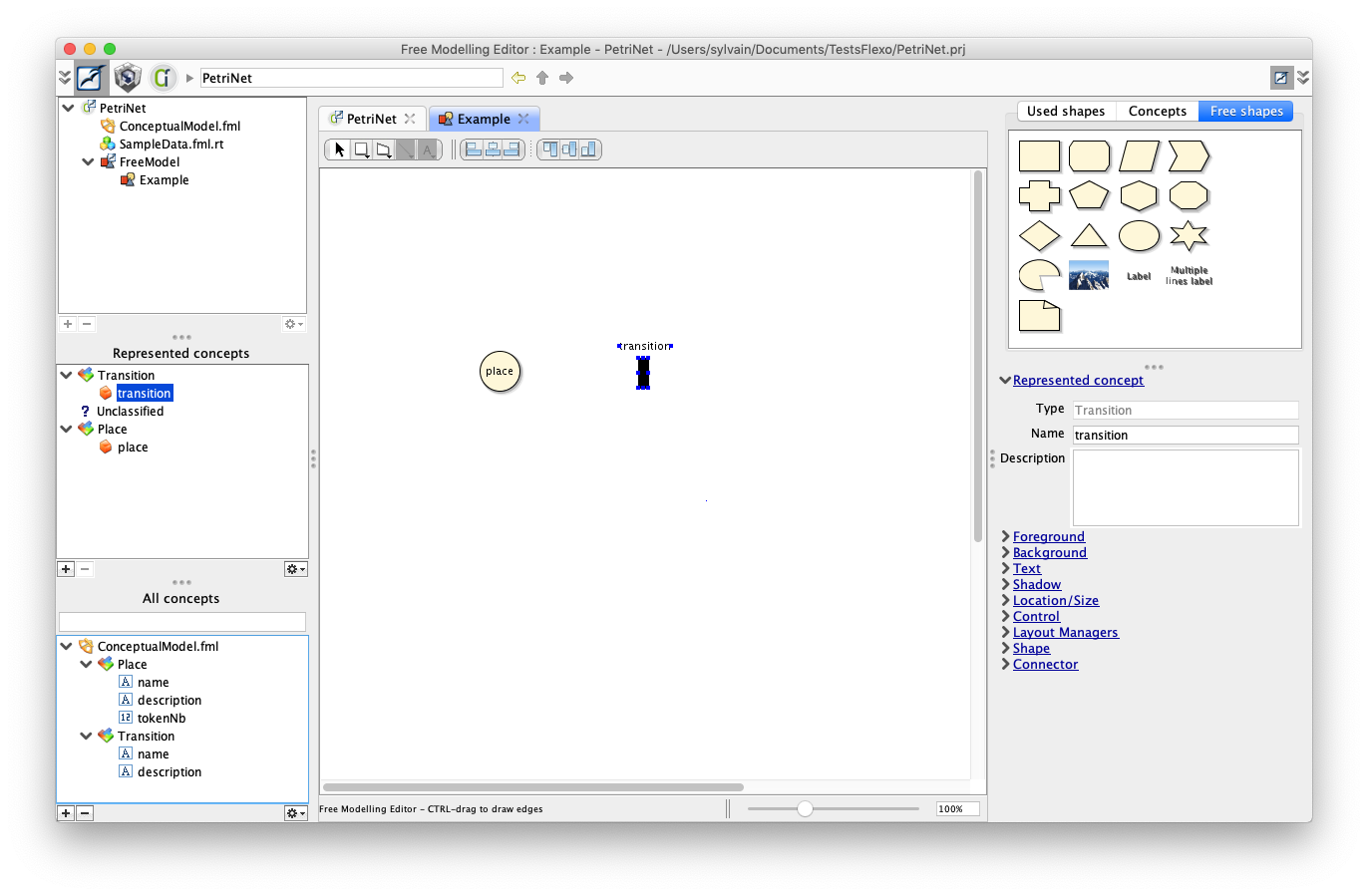
You should obtain something like this:
Then create a new concept Transition:
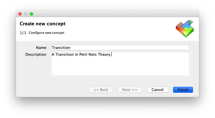
A new instance of Transition called 'transition' has been created:
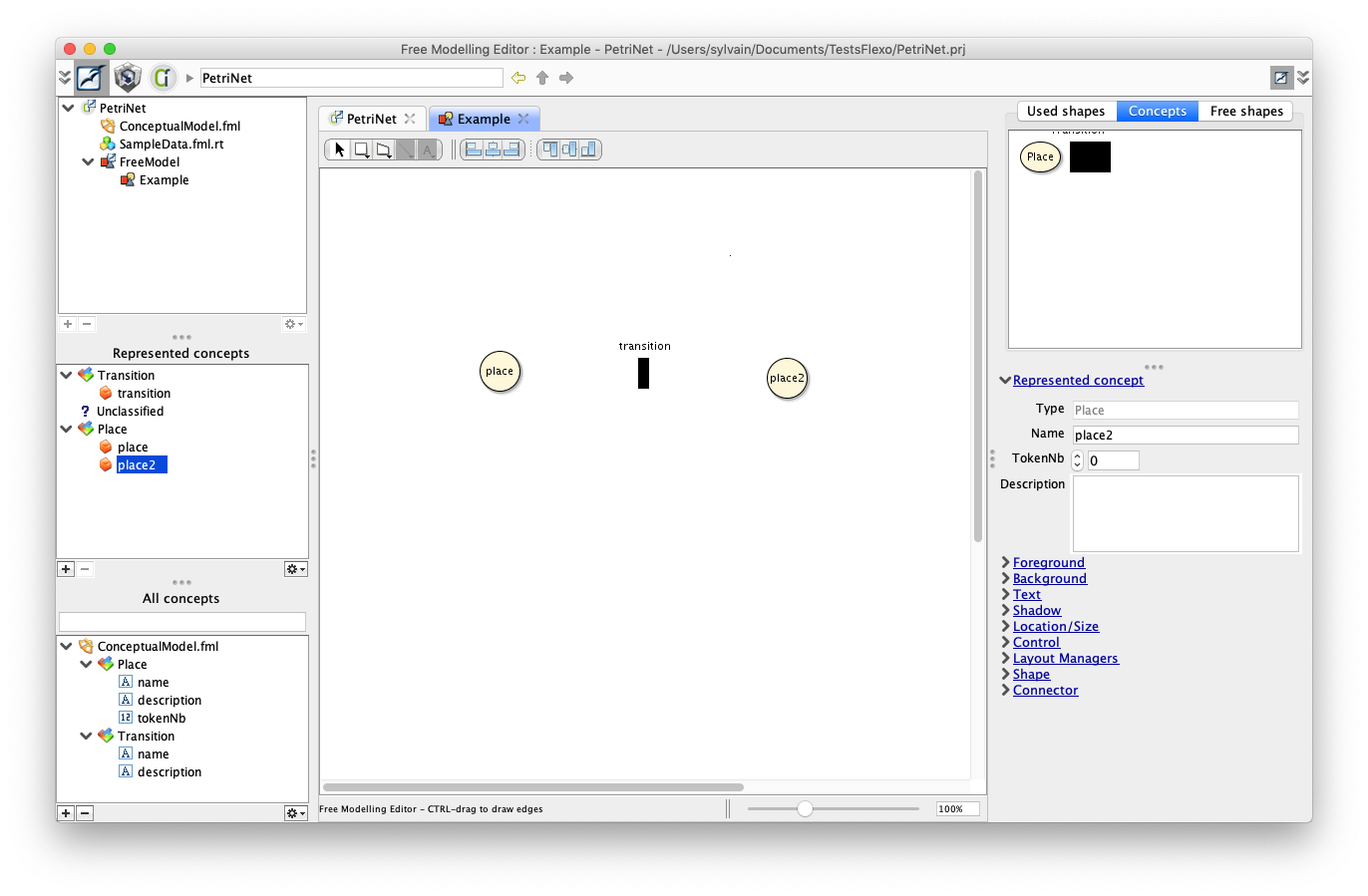
8. Instantiate an other Place
Select the 'Concept' palette on the right side, and drag a new Place on the diagram.
You should see an other instance of 'Place' concept appearing in the diagram.
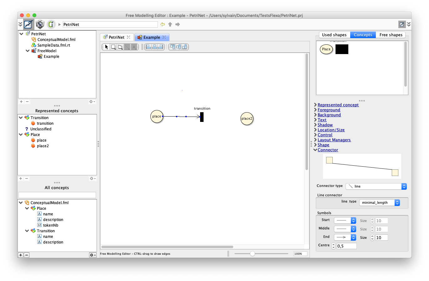
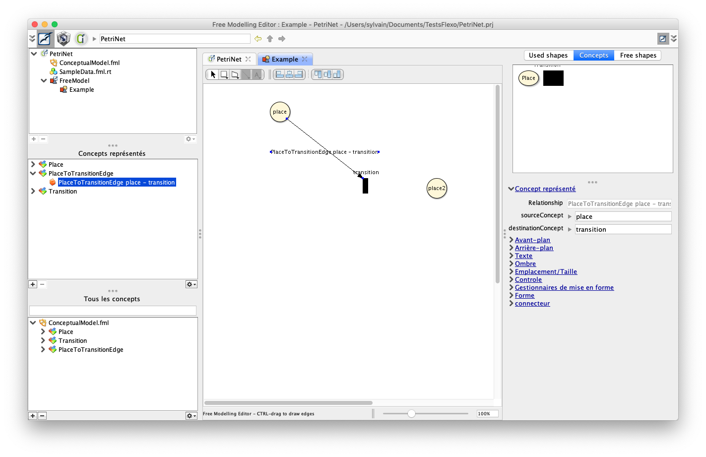
9. Create edges
It's time now to define some edges linking places to transitions, and transitions to places.
To do so, CTRL-click on first place, and draw an edge to 'transition'.
Select newly drawn connector, open 'Connector' inspector, and set terminal of edge to be a 'arrow' connector
Then right-click on connector, and select 'Create new concept'
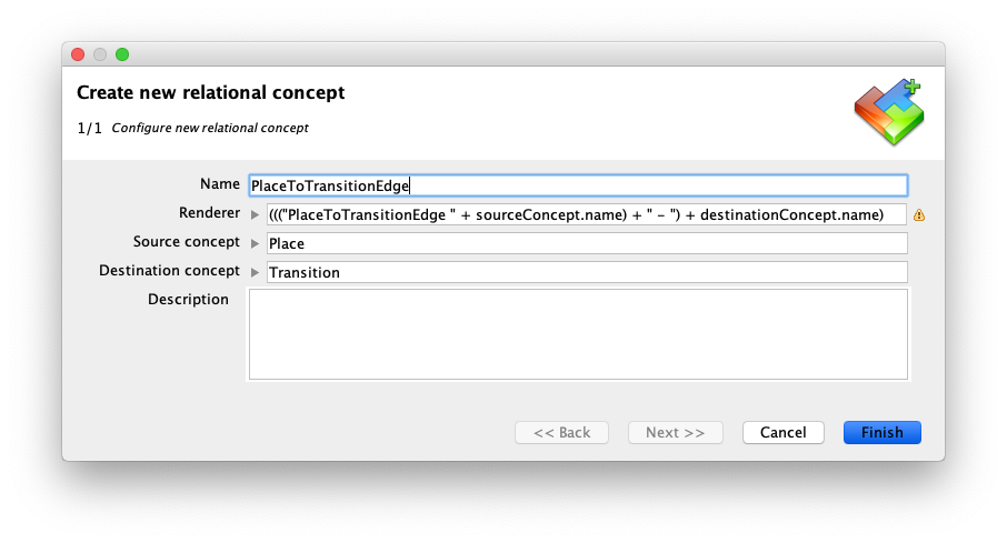
Leave default configuration.
This creates a new concept called PlaceToTransitionEdge, with a unique instance linking 'place' to 'transition'.
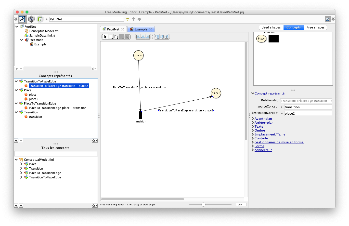
Do the same for the TransitionToPlace concept: draw a connector, and create related concept.
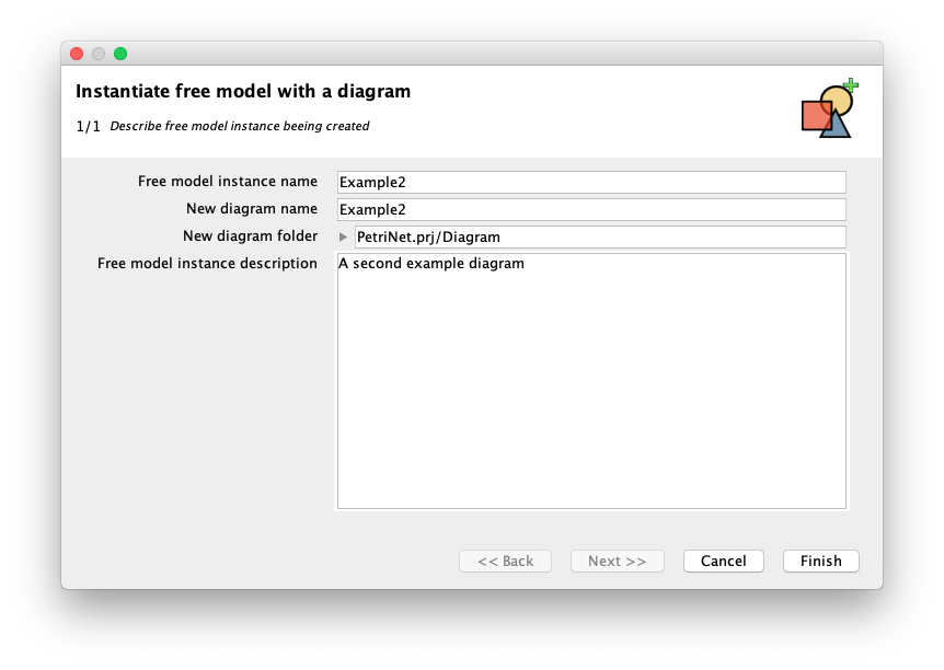
10. Create a new example diagram
A first graphical editor is now ready to use.
To test it, right-click on 'FreeModel' above 'PetriNet' project on the top-left browser, and select 'Instantiate diagram free model' to instantiate a new example. Call it 'Example2' as suggested.
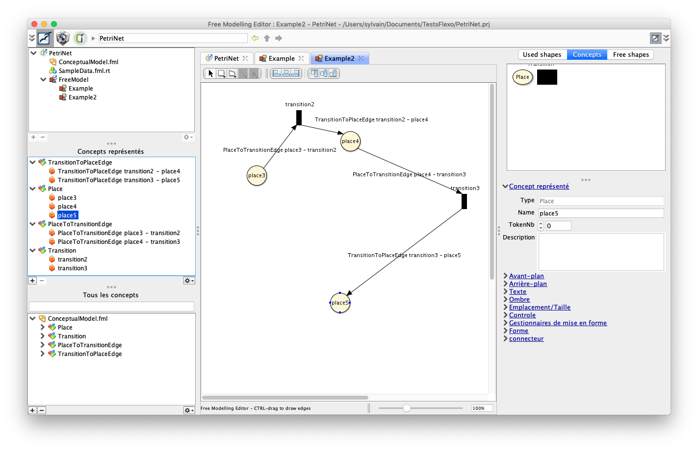
A new editor opens.
Select the 'Concepts' palette, and drag 3 places 'place3', 'place4' and 'place5'. Also drag transitions 'transition2' and 'transition3'. Connect those places and transitions (let the cursor stay on a shape, and drag using floating palette).
11. Start to edit conceptual model
The FreeModelling Editor is a good starting point to elicit concepts and build a new graphical editor.
We may now use the Openflexo Modeller to refine our models and graphical representations.
Right on the 'Openflexo Modeller' module icon on the top-left panel, to open Openflexo Modeller.
The left browser shows all resources that have been created/edited through the FreeModelling design process:
- ConceptualModel.fml: the conceptual model of Petri Net, with 'Place' and 'Transition' concepts
- SampleData.fml.rt: an instance of that conceptual model: our sample data
- FreeModel.fml: the meta-model of graphical editor encoding a Petri Net as a diagram
- Example.fml.rt and Example2.fml.rt: instances of that graphical editor (Petri Nets diagrams)
- FreeModel.diagramspecification: specification of a Petri Net diagram
- Example.diagram and Example2.diagram: pure diagrams encoding graphical representations
Lets double-click on ConceptualModel.fml to discover Petri Net meta-model just being created.
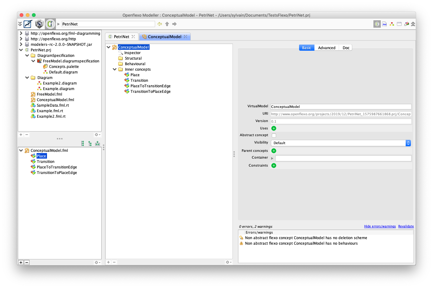
We see the 4 concepts that have been created. Double-clinking on concepts allows to edit them.
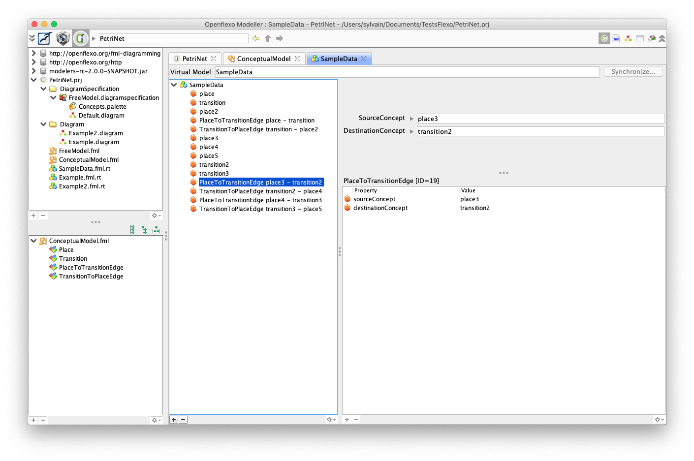
Lets double click on SampleData.fml.rt to discover our sample data.
Lets double click on FreeModel.fml to discover diagram FreeModel.
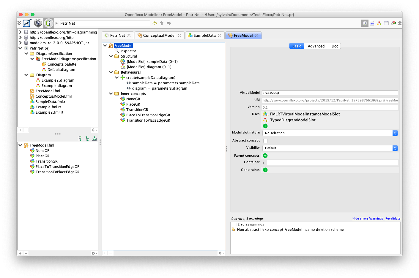
Concepts in that free model are federated concepts linking a concept to a graphical representation.
Double-click on PlaceGR for example. Then click on 'Diagram perspective' on the top-right panel.
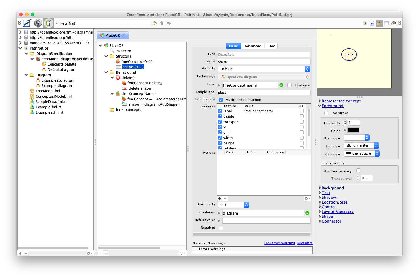
This concept has mainly two properties (roles):
- fmeConcept which is an instance of 'Place' concept (in the conceptual model)
- shape which is the graphical representation of a 'Place' in the diagram
Select 'shape', edit a new example value (eg 'place').
Open 'Text' inspector. Check 'Is floating label'. The label may be moved in the preview panel.
Edit bound label property of that shape.
First check read-only to declare it as a read-only label. Then instead of
fmeConcept.name
also display number of tokens inside the place. Label should be for example:
fmeConcept.name + "/" + fmeConcept.tokenNb
When reopening Example2 you see that labels of places are now something than: place3/null
It means that the tokenNb was never initialized.
To do so, open the conceptual model, double-click on Place concept. Expand create(conceptName) behavior. Select unique statement:
name = parameters.conceptName
Then click on the '+' button in the bottom left of the browser to add a new statement.
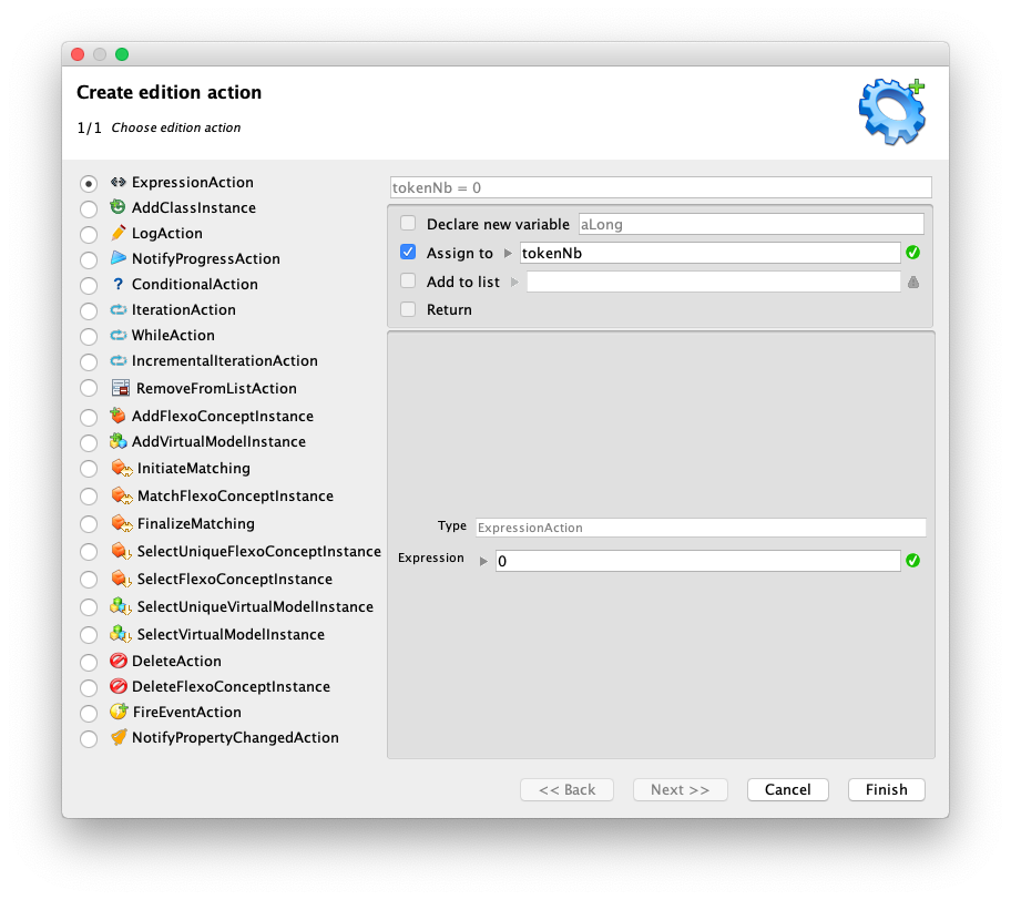
Select 'ExpressionAction', check 'Assign to' and fill in with 'tokenNb', then set expression to 0 and click 'Finish' to add that assignment expression:
tokenNb = 0
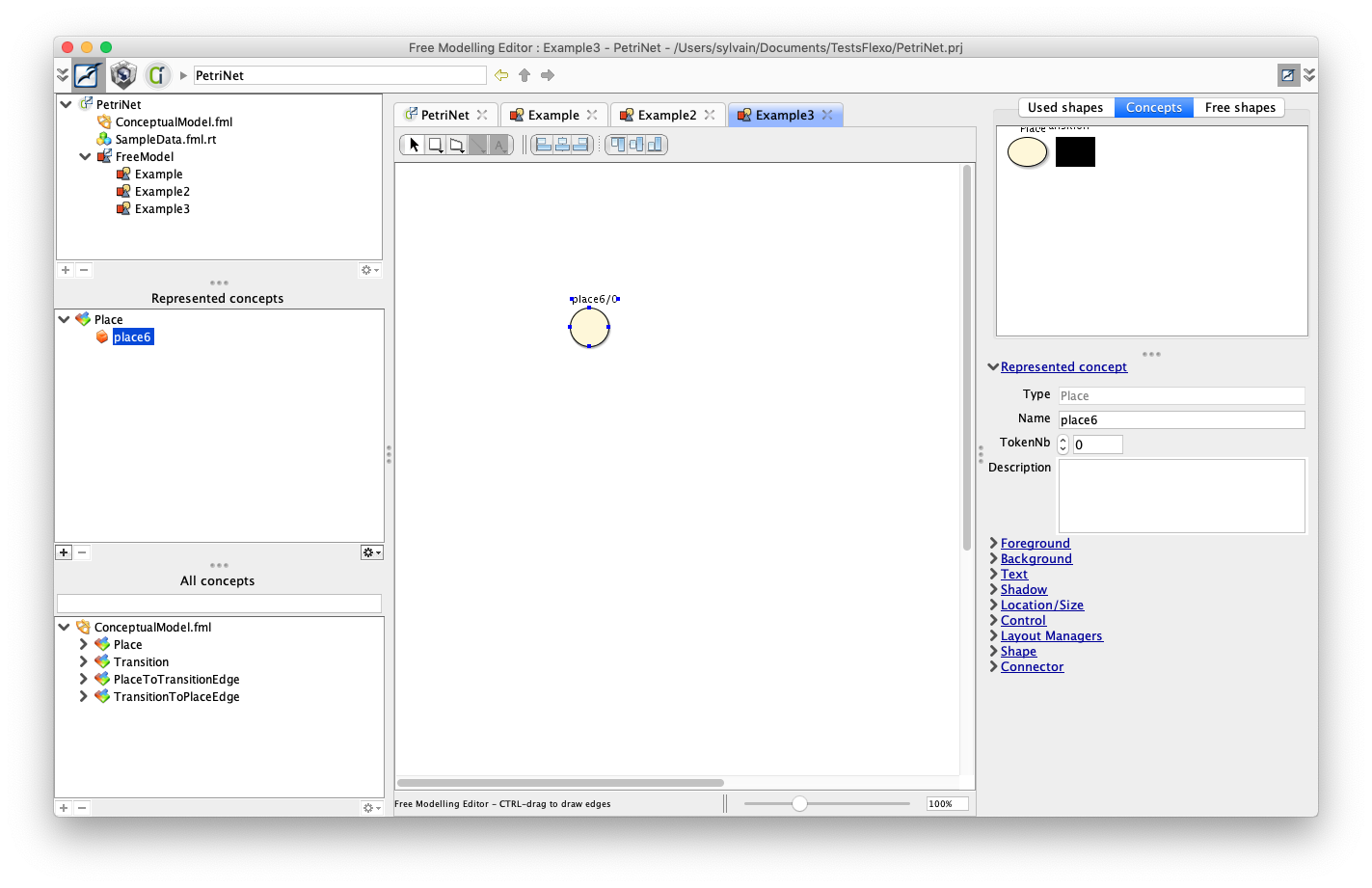
Then test this while going back to the FreeModellingEditor.
Create a new ExampleDiagram, called 'Example3', and drag a new Place. The place is well instantiated with the right number of tokens, and with a floating label displaying 'place6/0'
Using the same scheme, you can change the label rendering of edges to have a lighter display.
12. Abstract edges in conceptual model
We want now to define a 'weight' property on edges (PlaceToTransitionEdge and TransitionToPlaceEdge).
Instead of doing it twice, we would like to define a inheriting scheme.
To do so, switch back to Openflexo Modeller, and open ConceptualModel.fml
Right-click on ConceptualModel.fml, and select New > FlexoConcept
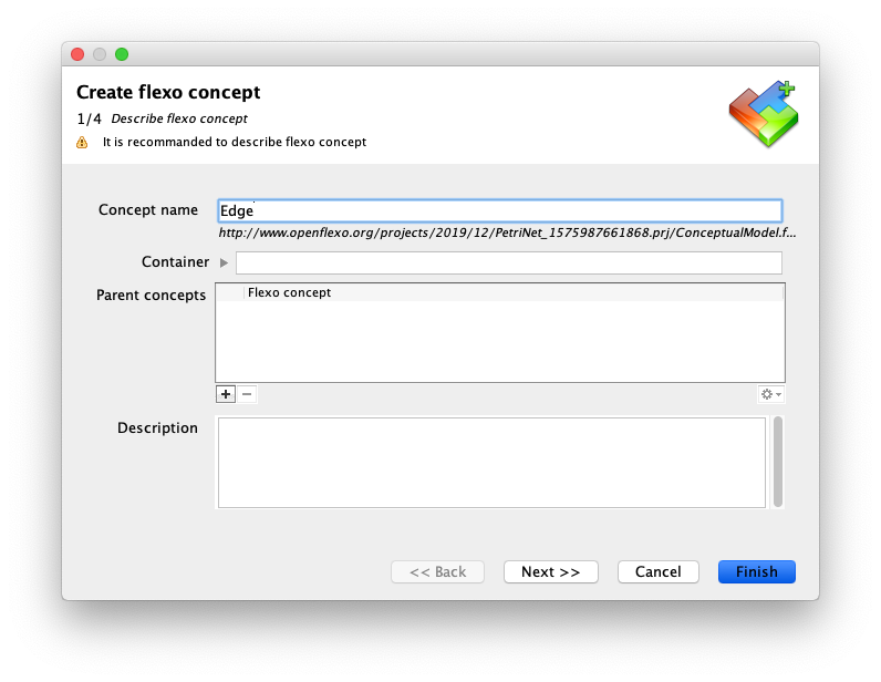
Abstract Edge concept has been created.
We should now declare Edge as parent concept for PlaceToTransitionEdge and TransitionToPlaceEdge
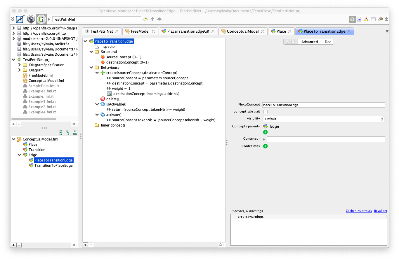
Double-click on PlaceToTransitionEdge. Click on '+' icon beside parent concepts and declare Edge as parent concept.
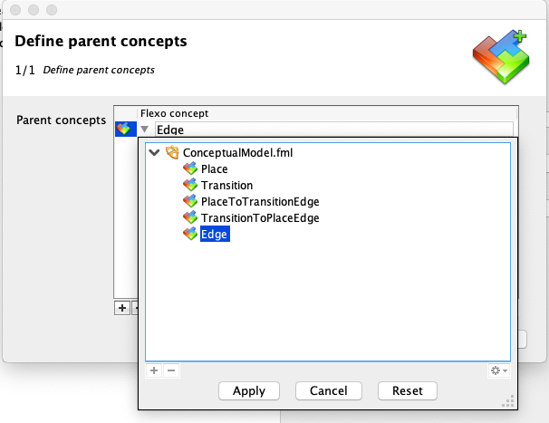
Do the same for TransitionToPlaceEdge.
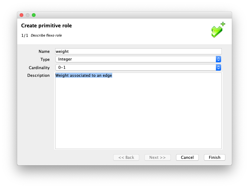
Then double-click again on Edge concept, select 'Structural' facet, and select New Property > Create primitive role
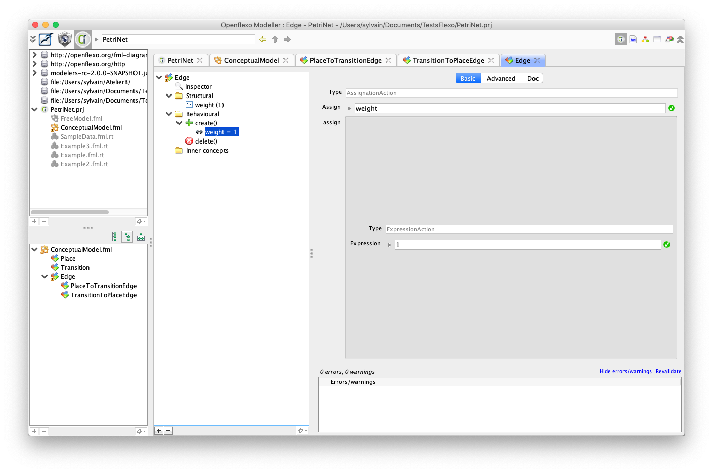
Select default constructor and add assignment to default value:
weight = 1
You should finally obtain this:
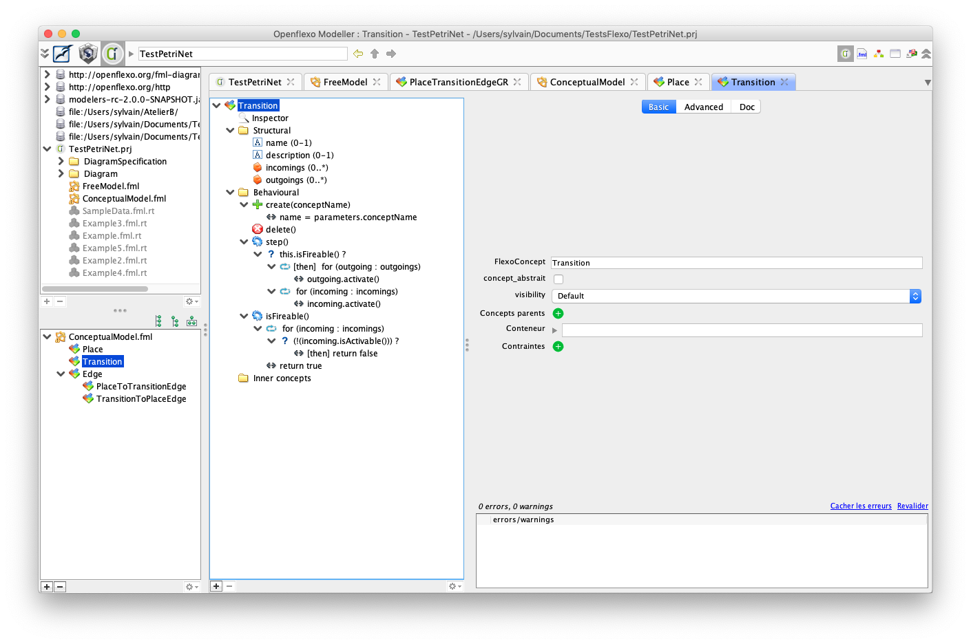
13. Declare references for edges in Transition
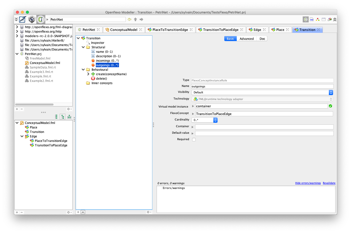
Edit Transition concept.
We must now declare references to incoming and outgoing Edges
Right-click on Transition structural facet, and select New Property > Select FlexoConceptInstance role
Create 'incomings' property with multiple cardinality storing references to all incoming edges
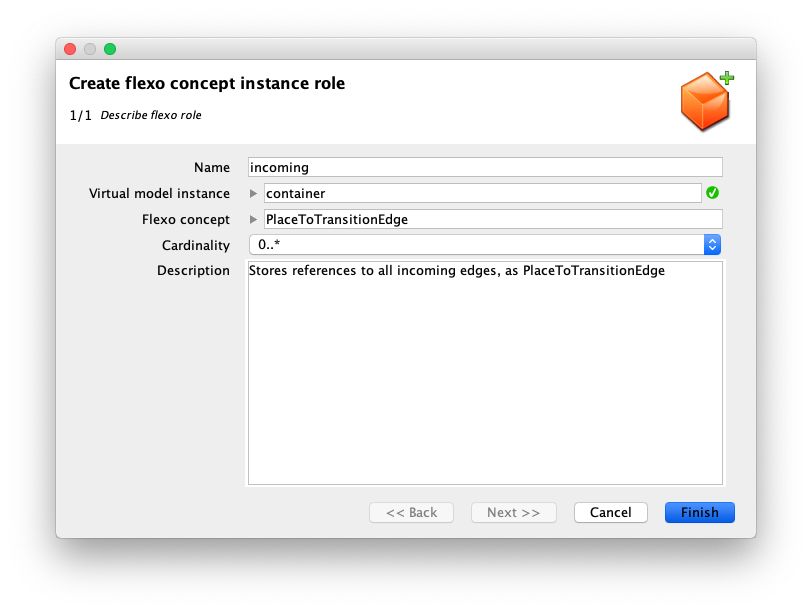
Do the same for outgoings property.
Now, go to PlaceToTransitionEdge constructor, and add to statements:
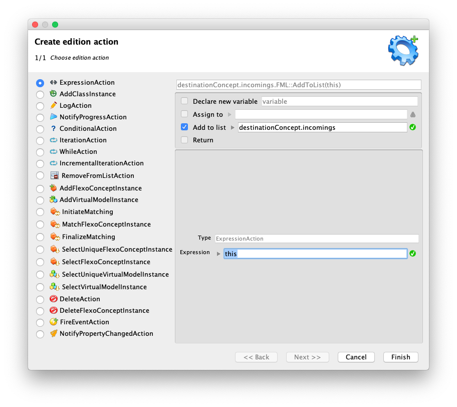
Do the same in TransitionToPlaceEdge:
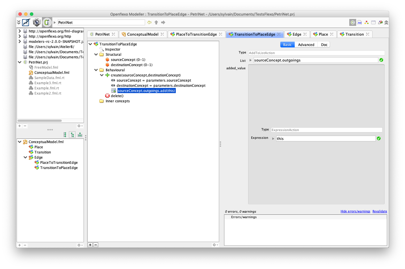
All the transitions now "know" about their incoming and outgoing edges
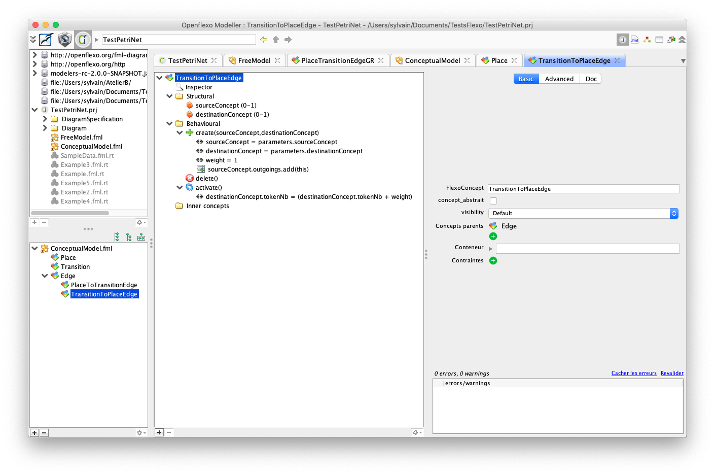
14. Define PlaceToTransitionEdge activation
This edge can be activated if the number of tokens in source concept is greater or equal to the weight of the edge.
To implement this, declare those two behaviors in PlaceToTransitionEdge (as ActionScheme):
isActivable() { return (sourceConcept.tokensNb >= weight); }
and:
activate() { sourceConcept.tokensNb = (sourceConcept.tokensNb-weight); }
You should obtain this:
15. Implement activation for TransitionToPlaceEdge
Define an activate() behavior for PlaceToTransitionEdge
16. Finalize Transition behavior
Define now Transition behavior:
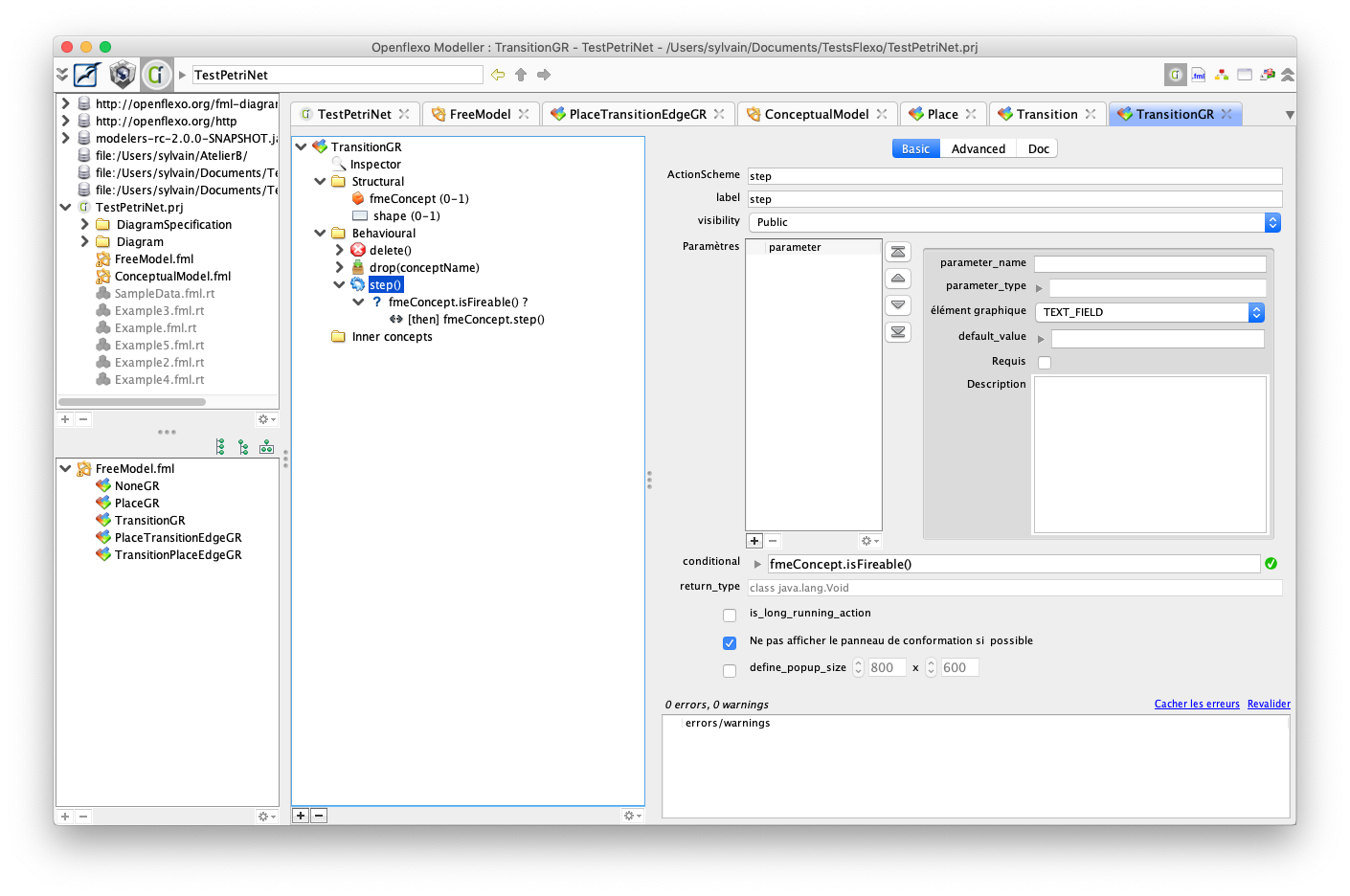
Finally expose behavior in an ActionScheme in TransitionGR.
It is really important to set visibility to public to have action available in graphical editor.
17. Test final editor
Switch back to FreeModelling editor to instantiate a new example.
Draw this Petri Net:
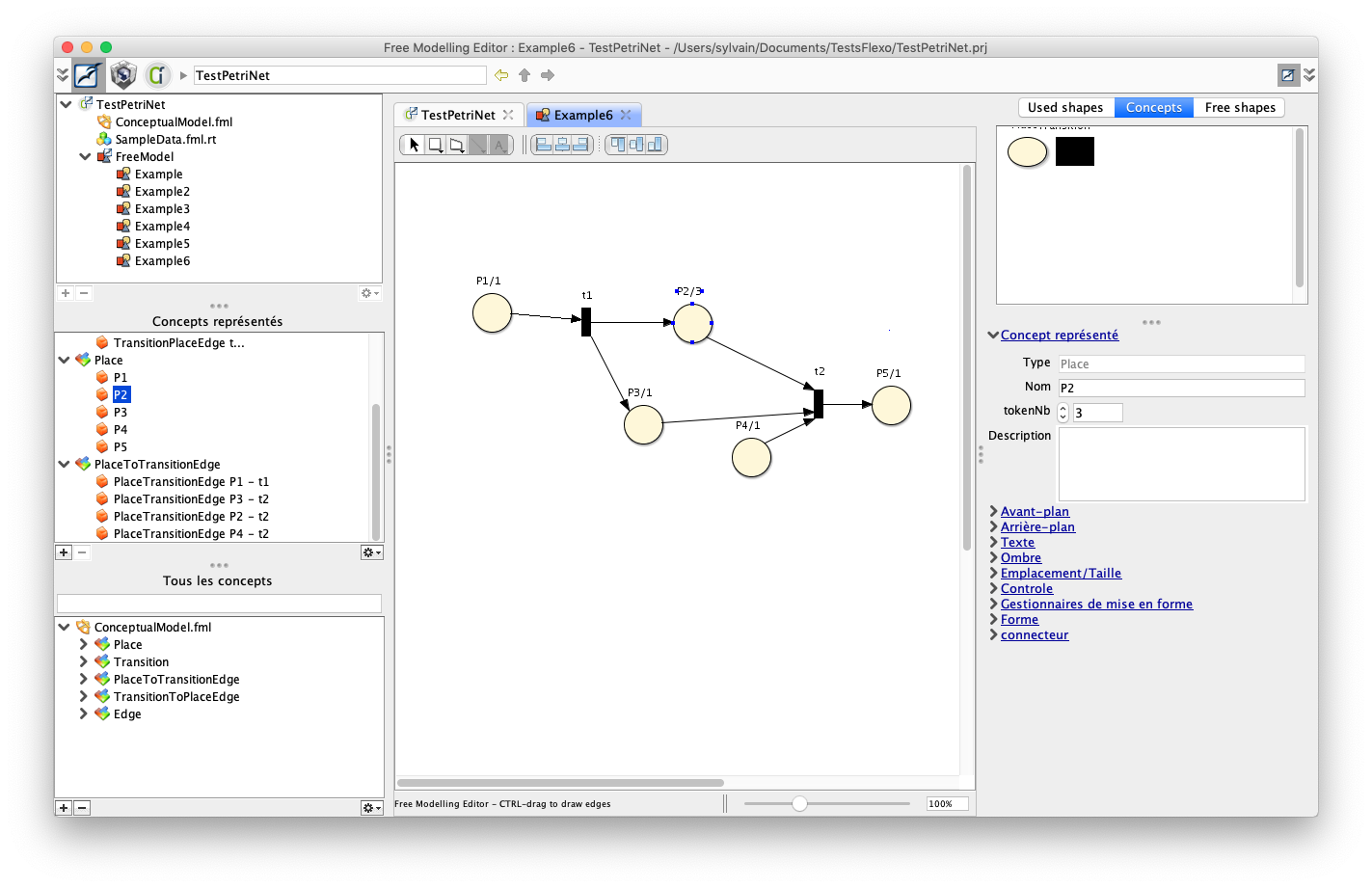
Transitions may be executed using right-click on transitions.