Tutorial 2 : Create diagram editor using the FreeModellingEditor
In this article, you will learn how to get started in creating a basic diagram editor while using the FreeModellingEditor.
1. Purpose of this tutorial
The purpose of this tutorial is:
- To discover how to highlight some business concepts with the Openflexo FreeModellingEditor tool
- To build a basic graphical editor (diagram-based) of those concepts
2. Download Openflexo
As a preliminary phase, you should get a recent Openflexo distribution (Openflexo Semantics+ 2.0.1 is recommanded)
Download it on:
3. Launch Openflexo FreeModellingEditor and create a project
Launch Openflexo, and choose the FreeModellingEditor.
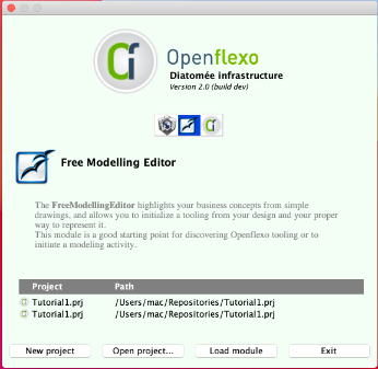
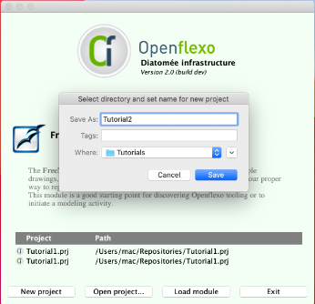
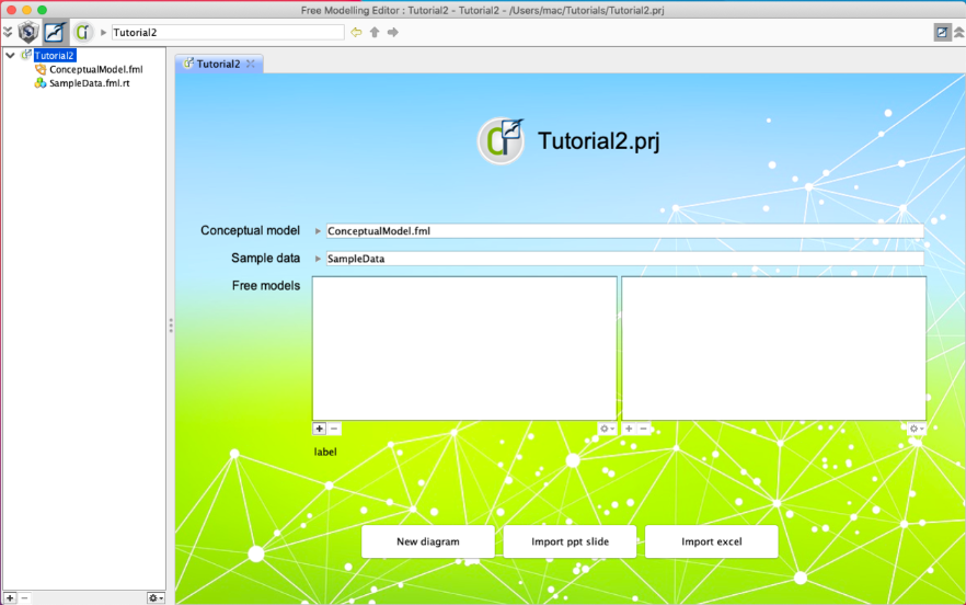
Click on New project, choose a name, here Tutorial2.prj
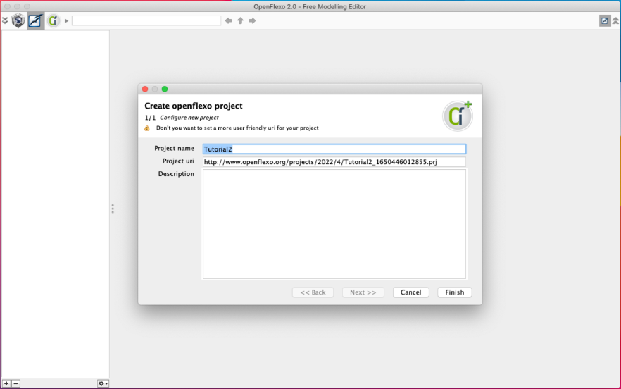
Set the project name, uri and description the click Finish.
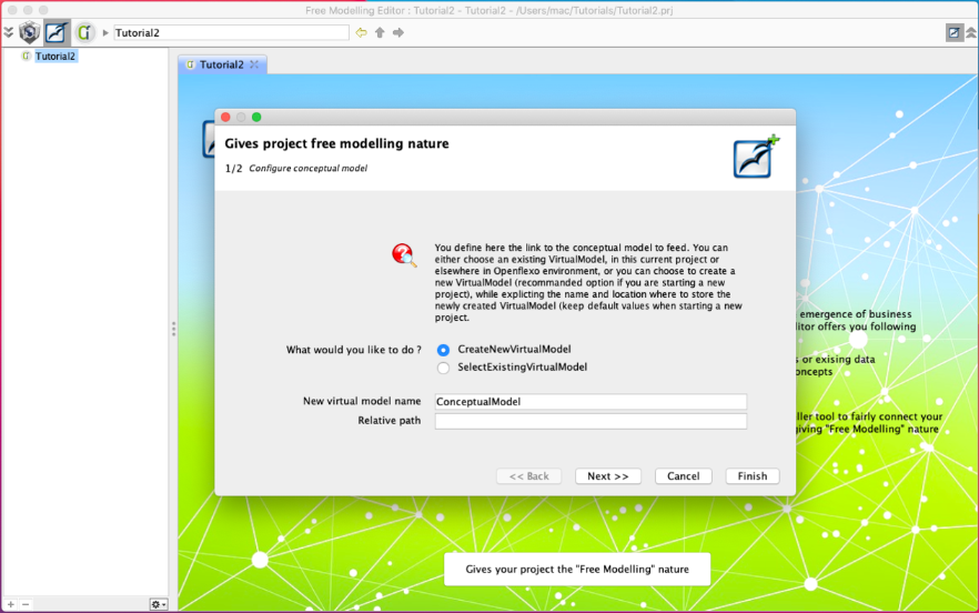
For the project free modeling nature, you can just click Finish.
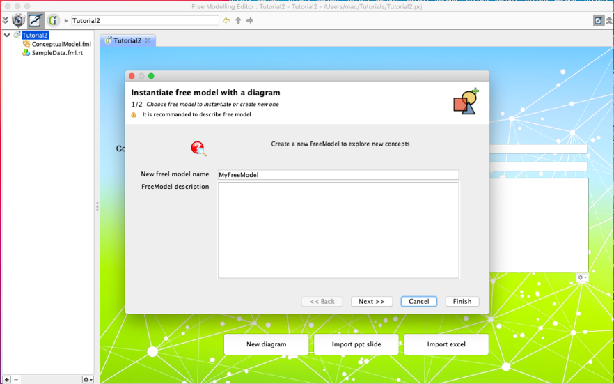
4. Create a FreeModel
Click on New diagram button at the bottom.
Set the name and the description of the FreeModel then click Next.
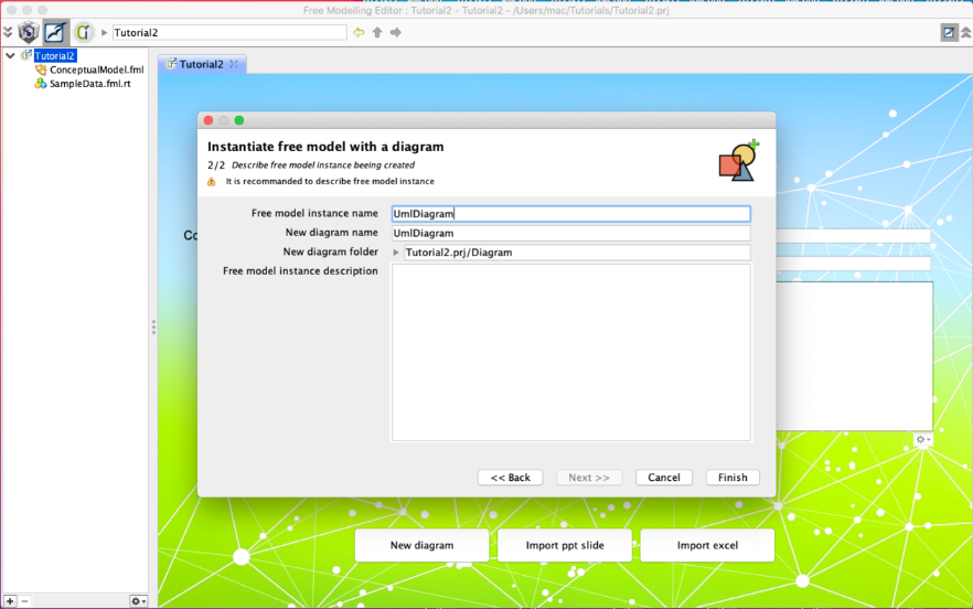
Give your diagram a name then click Finish.
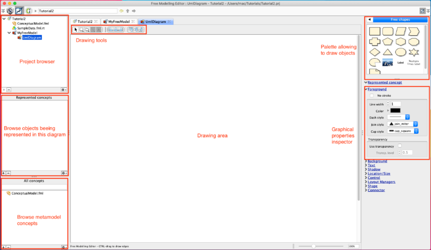
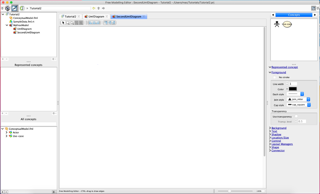
You should obtain this blank diagramming area.
The following screenshot shows the different panels.
On the left side of the screen, you find 3 browsers.
- The upper one allows to browse the project. It shows the different FreeModels and inside diagrams.
- The middle one present the instances of some concepts that are represented on related diagram.
- The bottom one present the metamodel concepts.
On the right side of the screen, the top component represent the 3 palettes that are usable in the context of the FreeModellingEditor:
- "Free Shapes" palette represent some basic shapes that can be dropped in current diagram
- "Used Shapes" palette represent all the different shapes that are used in current diagram
- "Concepts" palette represent all the shapes of the metamodel concepts.
Graphical properties inspector completes the view, by providing graphical edition features to the diagram elements.
5. Draw an example diagram
Suppose that we are working on UML tooling, and that we want to build a diagram editor for the UML use cases diagrams.
We are supposed to be able to model such models:
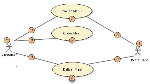
Let's start to draw this example on the FreeModellingEditor.
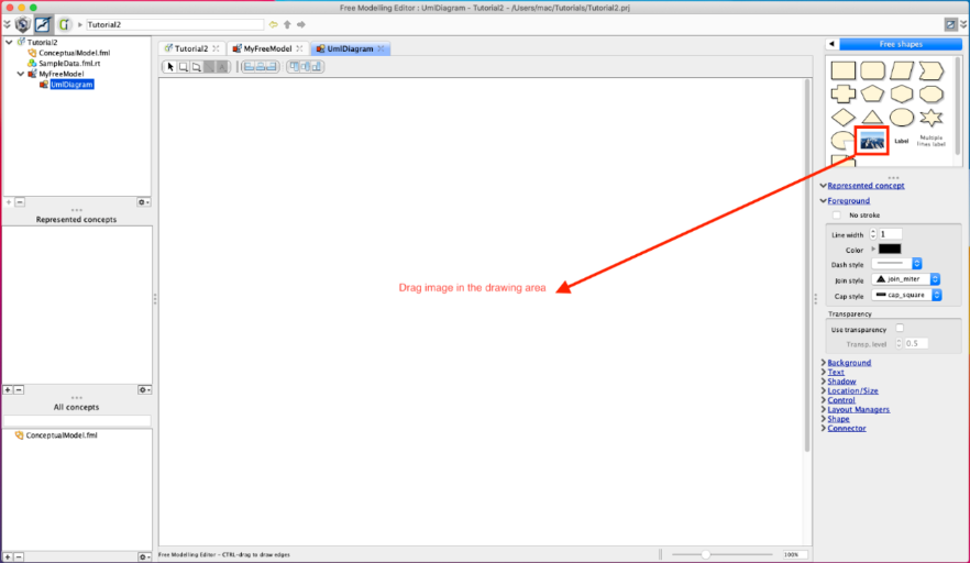
Let's draw an actor, by dragging image palette item.
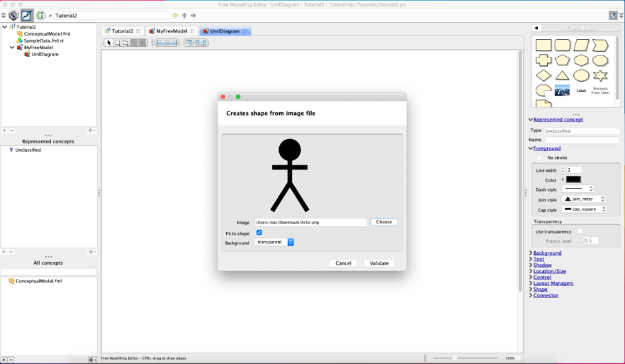
A dialog box opens. You have to choose a file on the disk (for example Actor.png, which should be put in Tutorial2.prj)
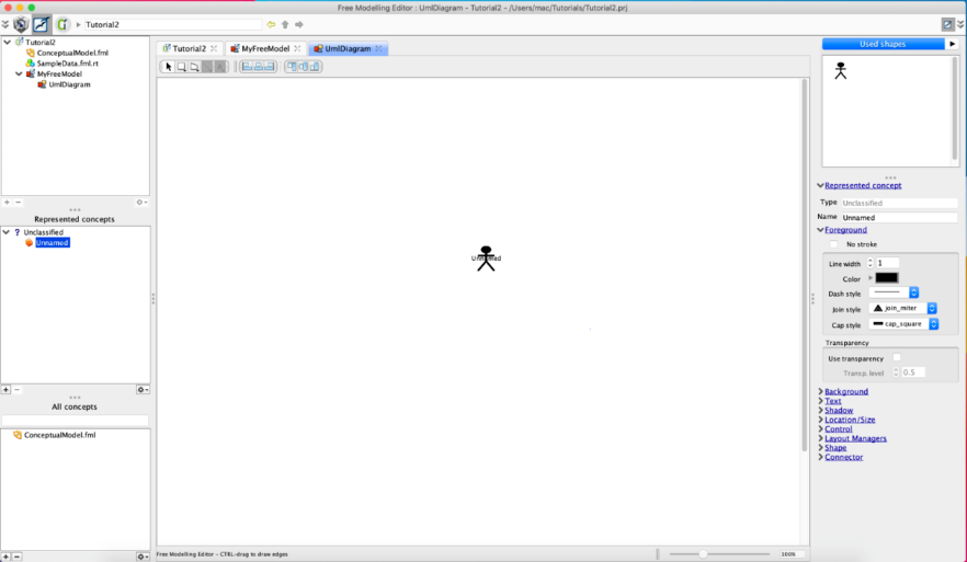
You have created the shape that will represent an Actor (in a UML Use-Case diagram). No that the Used shapes palette has now a unique element showing an actor.
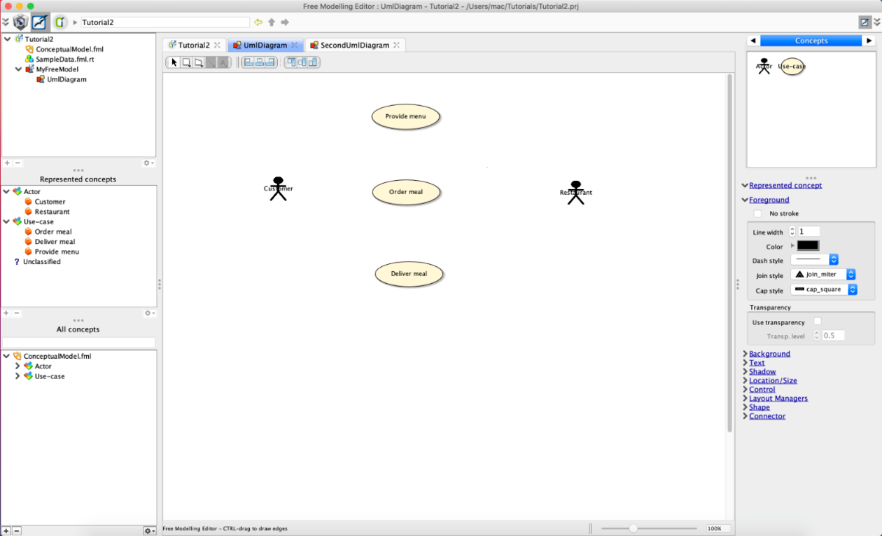
Go back to the Free shapes palette. Drag oval shape on the drawing to represent a use case.
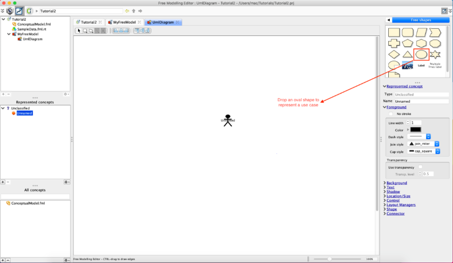
You have created the shape which represent a use case. You can move it on the drawing.
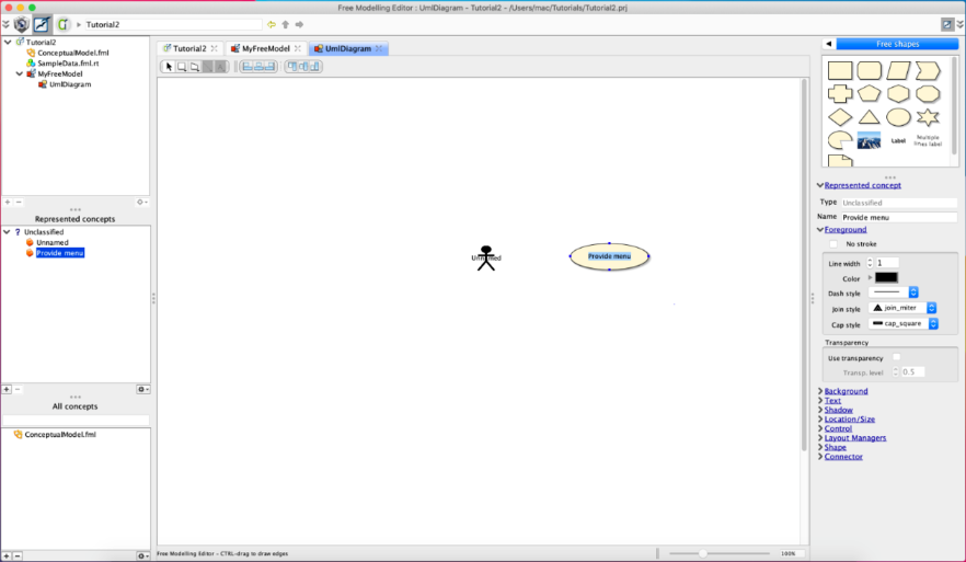
You may now double-click on labels of created shapes and edit a name. For example name the use-case "Provide menu".
6. Declare concepts
It's time now to declare concept UseCase. Select the "Provide menu" shape. Right-click and select Create new concept.
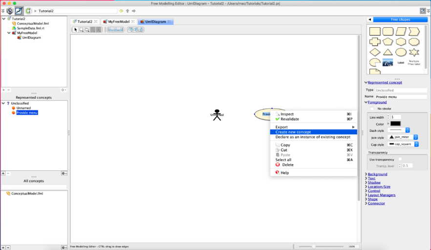
Enter a name and a description of the new concept, and press finish.
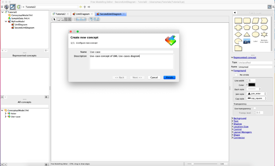
Do the same for the actor. Name it "Customer" and create a new concept "Actor".
You can now draw the full diagram as shown in example diagram we have shown at the beginning of this tutorial. Switch again to Used shapes palette. Use the palette to drop an other actor and some other use cases. You should for example get this:
Note that the elements "Provide menu", "Order meal", "Deliver meal", "Customer" and "Restaurant" are all identified and classified relatively to the two concepts UseCase and "Actor".
7. Finish edit diagram and get your first diagram editor
You can now draw connectors (lines) between elements. To do so, press CTRL key and drag a line from a shape to another shape.
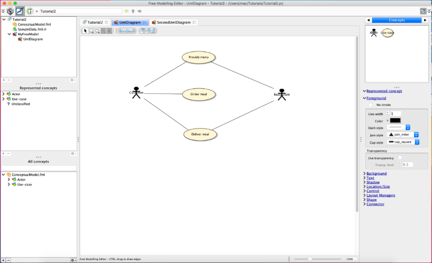
Your first diagram is now finished. And you have got your first graphical editor for a UML Use-Cases Diagram Model !
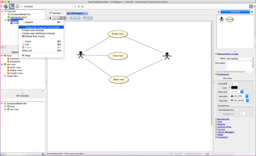
8. Using newly created diagram editor
It's now time to launch this diagram editor to create new diagram (test and use the graphical editor just being built)
To do so, right click on MyFreeModel then choose Instantiate diagram free model
This will create a new diagram. Call it "MyFirstUMLUseCaseDiagram".
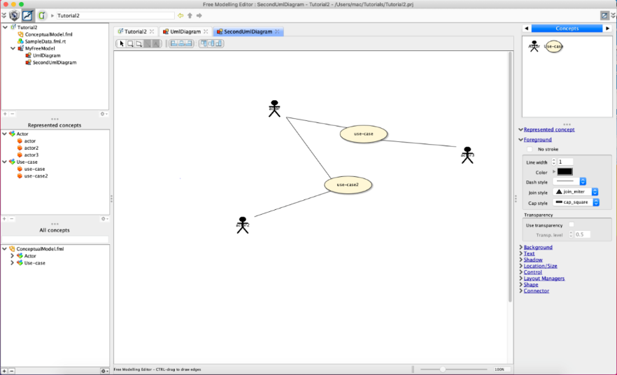
You can edit a new diagram, such as:
This tutorial is now over.
We suggest you to launch the next tutorial (tutorial 3) if you want to enter deeply in the Openflexo Diagramming Technology (expert users)
9. Download tutorial project
You may download the tutorial project (Tutorial2.prj) on github (project integration-tests-rc)