Tutorial 1 : Getting started with the FreeModellingEditor
This article will introduce you to the FreeModelingEditor. It is a basic editor that allow you to develop modeling diagrams without any constraint of a specific modeling language. It is during the development of the model that you will enrich the modeling language (meta-model) and its associated tool.
The purpose of this tutorial is:
- To present the main concepts of the Openflexo FreeModellingEditor tool.
- To show how to develop and edit modeling diagrams composed from scratch and from existing powerpoint slides.
- To identify and declare some new business concepts from a modeling diagram (meta-model enrichment).
- To reference and declare some instances of identified business concepts.
Pre-requisites
This tutorial assumes that you have already downloaded and installed an Openflexo distribution (Openflexo Semantics+ 2.0.x recommended). If this is not the case, then download it from:
1. Creating a project
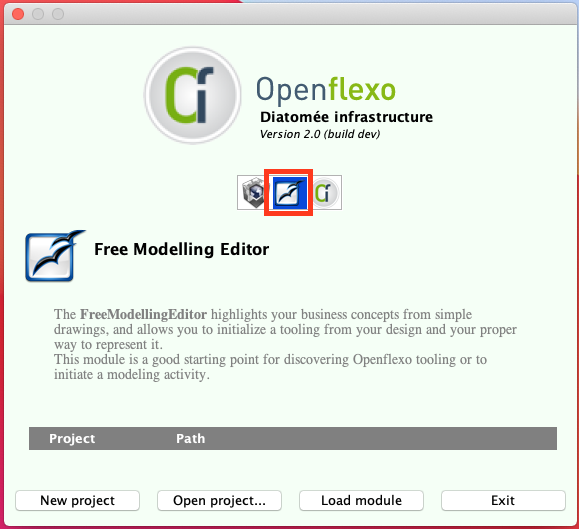
Launch Openflexo. On the welcome screen, choose the FreeModellingEditor as shown by the red square in the next Figure.
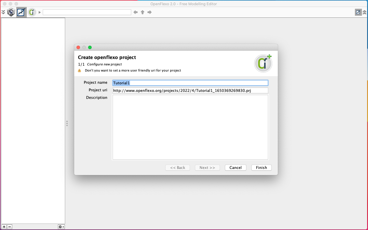
Click on New project then choose a project name and directory. We choose Tutorial1.prj in our example.
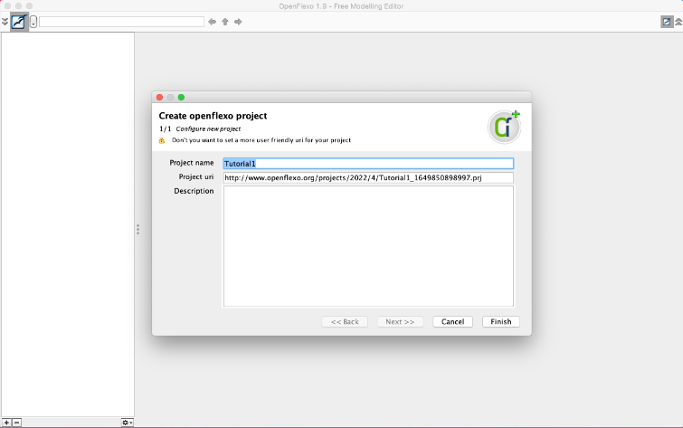
In the opened wizard, you can specify your project name, uri and description then click Finish.
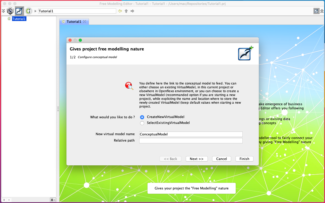
Another wizard will appear, choose your existing VirtualModel or create new one then click Finish.
This should launch the FreeModellingEditor (FME) module.
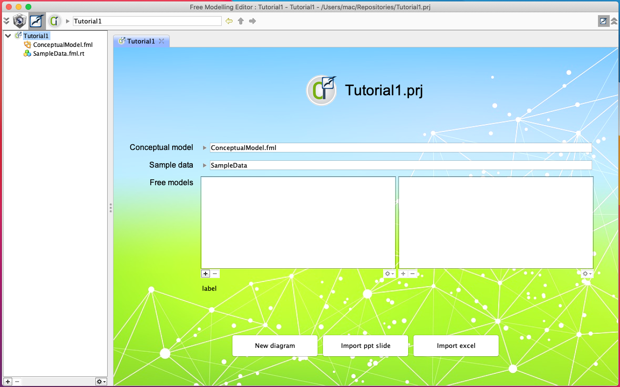
2a. Creating a Free Model from Scratch
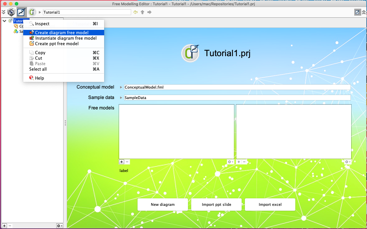
Once the FME module is launched, we can see it in the project explorer in the left pane. You can see an item that has the name of your project (Tutorial1 in our case). Right click on it and choose Create diagram free model.
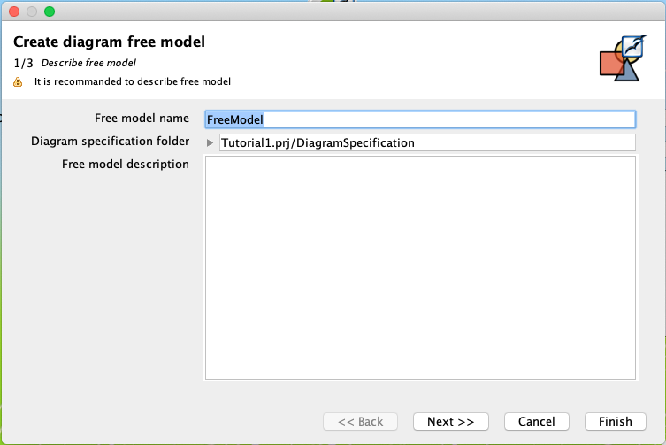
This shall open a wizard for the creation of a FreeModel. Give it a name and a description.
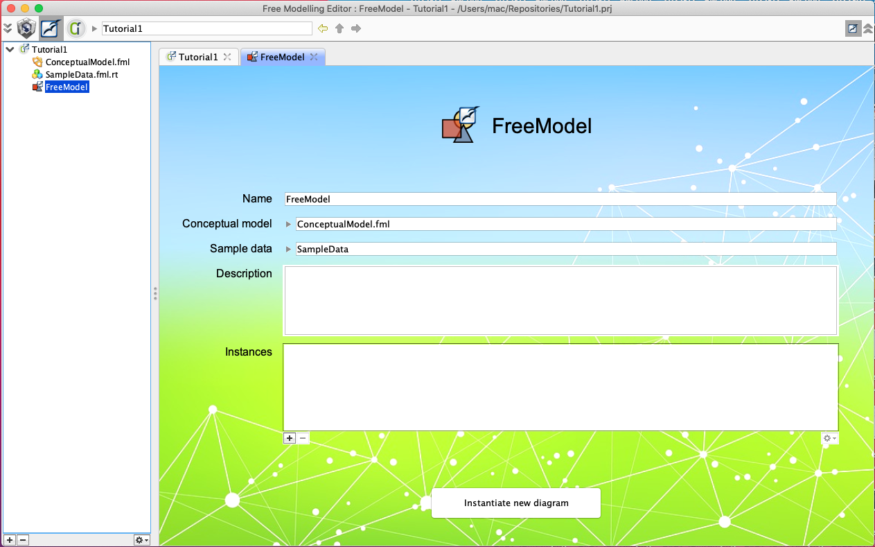
This created FreeModel should open in a new tab.
2b. Creating a Free Model from a Powerpoint slide
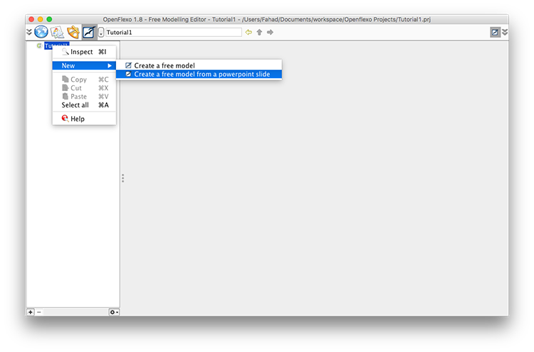
A FreeModel can be developed from an existing Powerpoint slide, where it will extract graphical representations from the file. In this case, right click on the name of your project in the project explorer (left pane of the tool interface) and choose Create ppt free model.
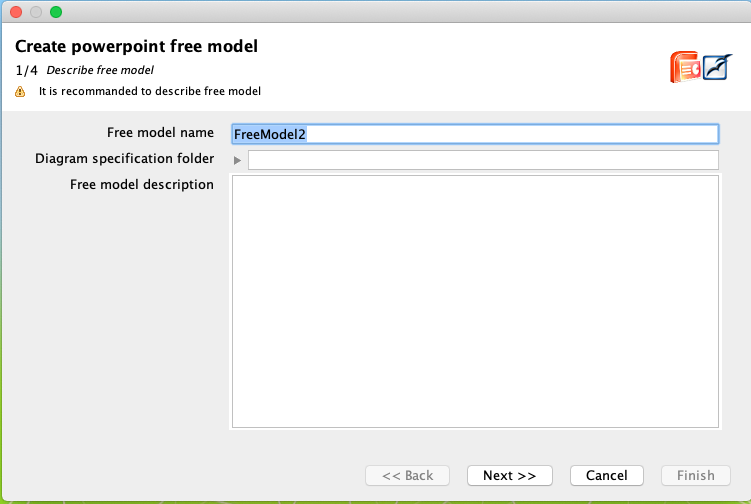
This shall open a wizard for the creation of a FreeModel. Give it a name, a description and you can set a Diagram specification folder then click Next.
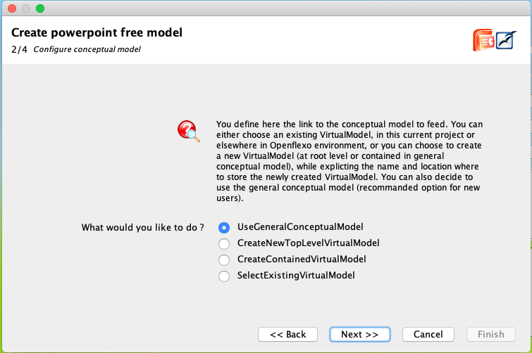
In the following screen, choose UseGeneralConceptualModel then click Next.
Next, choose UseGeneralSampleData then click Next.
It requires a Powerpoint slide file. Once it gets the file, it will populate the name and title field automatically. For the moment, we only support .ppt files, so your .pptx files won't work currently.
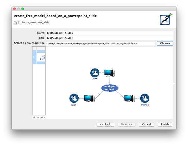
This shall open the modeling interface with graphics imported from the Powerpoint slide. Adjust the size of different panes, according to your liking.
3. Populating the Model
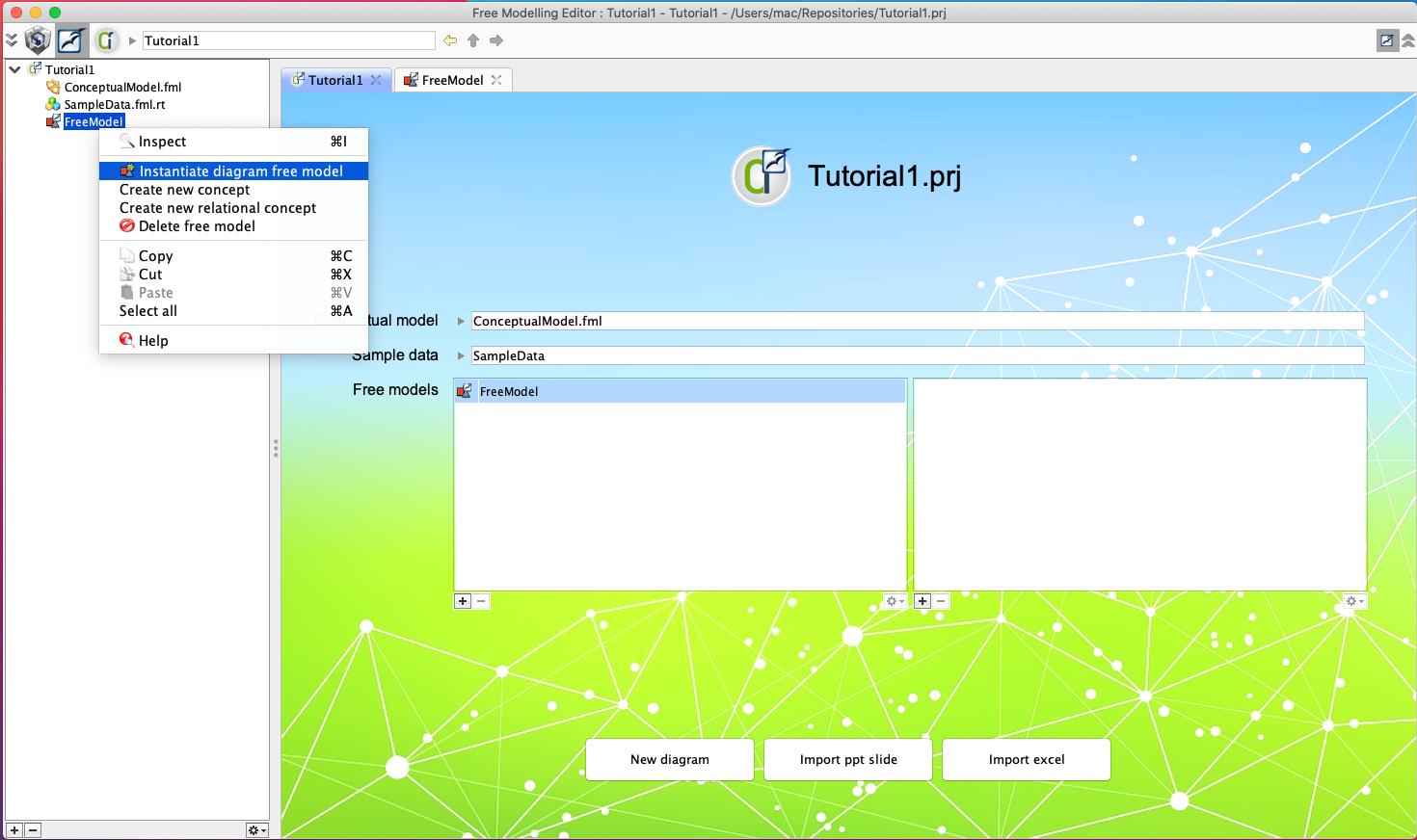
In order to populate the model we need first to instantiate a diagram from our FreeModel. To do that right click on the FreeModel then choose Instantiate diagram free model.
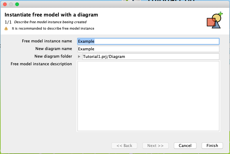
Give your diagram a name then click finish.
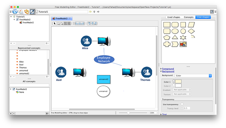
Before starting to populate the model with graphical items, it is important to understand the interface of the tool.
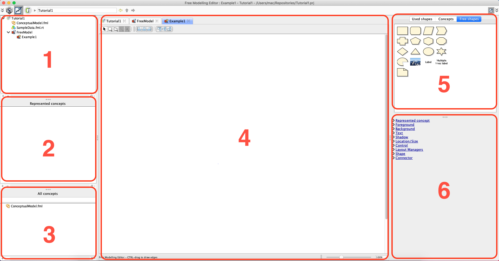
Free modeling view interface is organized in the following panes (numbers corresponds to appropriate pane in the figure) :
- This pane is a project explorer, which indicates the free models contained in current project.
- This pane shows the set of graphic instances in the drawing pane. These instances can be from a declared concept. In this case, they will be listed under that concept name. Instances that do not relate to any declared concept are listed under None concept.
- It displays a set of already declared concepts. None concept is used to gather all elements whose concept has not been identified yet.
- The drawing area is displayed in the center. Models are developed in this area.
- This zone displays three palettes:
- Used shapes palette offers all the shapes that are already used in the drawing area, either associated to a concept or not.
- Concept shapes palette presents all the shapes that are related to a declared concept, excepted for the None concept.
- Free shapes palette represents the shapes without any relations with a concept. They are used as building blocks for developing new models.
- This pane provides graphical properties that can be applied to shapes.
Once you know the interface, you can drag and drop shapes from the palettes to the drawing area for creating new models. This models serve as instance models. Once can identify different concepts from these shapes, so as to develop the language for our models (meta-models).
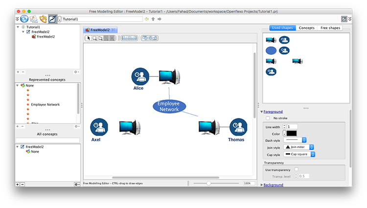
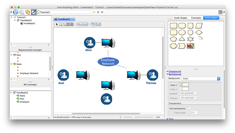
We are taking the FreeModel2 that we developed in the last step (2b) from an existing Powerpoint slide. We drop a circle and rectangle in the drawing zone from the Free shapes palette, so as to introduce new shapes to our model. We changed the background color of the rectangle to blue from the graphical properties pane. The resulting model is shown in the following figure.
4. Declaring new concepts
This tool allows the identification of new concepts from existing models. To declare a concept from an instance shape means to add a concept to the modeling language. To do this, we right click on the 'computer shape' and choose Create new concept.
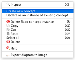
This opens a dialog box, where you enter the name and description of the concept Once this is done, we do the same creating an Employee concept from one of existing blue circles. This results in the following figure, where you can see the concepts in the left lower pane of the interface.

5. Declaring new concept instances
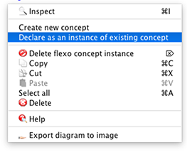
To declare a shape as an instance of an existing concept, we need to declare it as an instance of an existing concept. We right click on the blue rectangle and choose declare as an instance of existing concept.
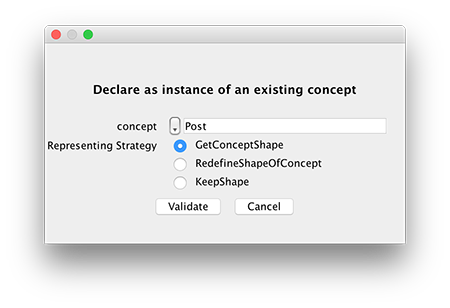
This opens a dialog box, where we can select the chosen concept from the drop down list. We also need to choose a strategy for its representation. GetConceptShape takes the shape of the declare concept, RedefineShapeOfConcept overrides the shape of the identified concept by current shape and KeepShape allows this instance to have existing shape despite being the instance of the selected concept.
We choose Post concept and select GetConceptShape.
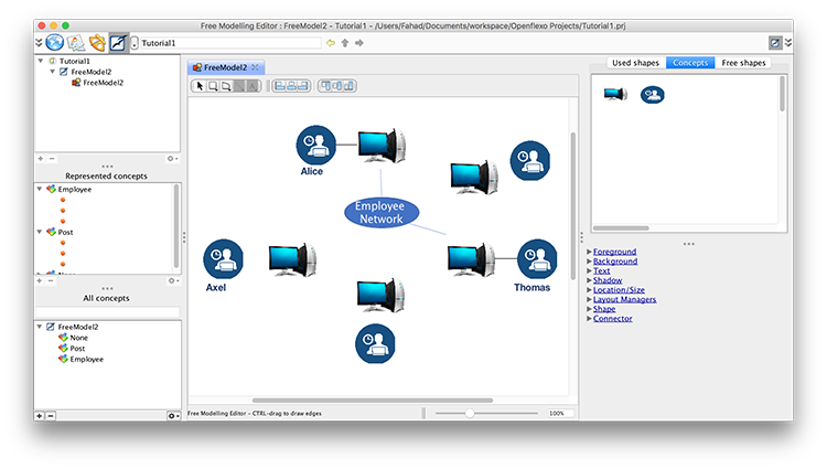
After validation a new instance should be visible in the concept/instance browser. We do the same process with the circle shape to identify it as an instance of Employee. The resulting model is shown in the figure below.
Once done, we can verify which instances are declared to be the instances of None and which are from Post or Employee from the represented concepts pane. Affecting a change to the concept, would apply that change to all its instances automatically.
6. Using the new editor
We have just created a graphical editor by playing with two concepts in the drawing zone. Ofcourse this is a very basic editor with only two concepts that we identified. It is just the start :)
You can select the concepts tab from the right top palette and it will bring the following interface. Now you can drag and drop the employees and posts like any other graphical editor.
Final Note: After going through other tutorials, you will be able to use free modeling with other views provided by the tool to develop complex editors.